Multifunctional energy resource system

An energy system and multi-functional technology, applied in energy input, chemical modification of combustible gas, gas production, etc., can solve the problems of thermal efficiency reduction, etc., and achieve the effect of improving utilization rate, efficient utilization, simple utilization and reasonable utilization

Active Publication Date: 2008-10-15
中科思道(南京)储能技术有限公司
View PDF0 Cites 37 Cited by
  • Summary
  • Abstract
  • Description
  • Claims
  • Application Information

AI Technical Summary

Problems solved by technology

Separation of CO before combustion 2 system, the thermal effic

Method used


Image

  • Multifunctional energy resource system
  • Multifunctional energy resource system
  • Multifunctional energy resource system

Examples


Embodiment Construction

[0061] In order to make the object, technical solution and advantages of the present invention clearer, the present invention will be described in further detail below in conjunction with specific embodiments and with reference to the accompanying drawings.

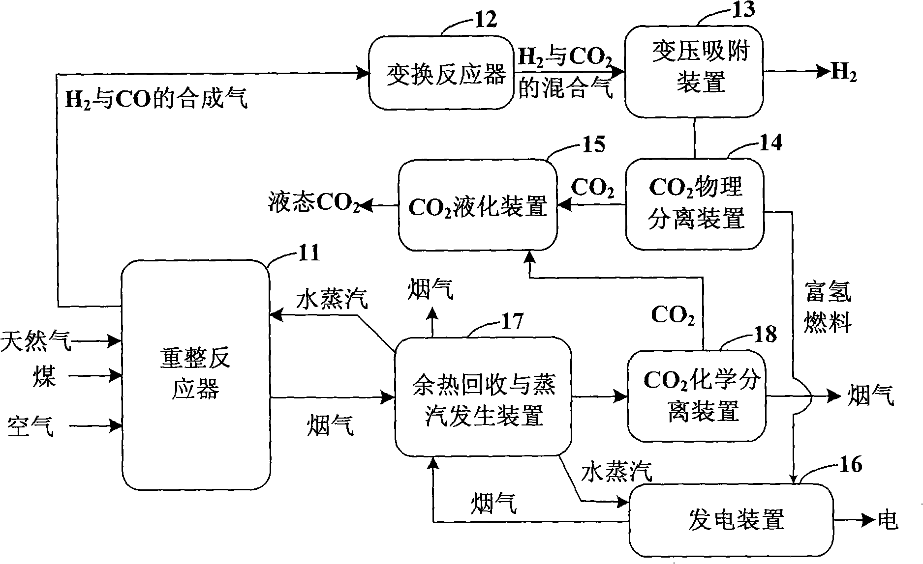
[0062] Such as figure 2 as shown, figure 2 It is a schematic structural diagram of the multifunctional energy system provided by the present invention. The multifunctional energy system includes a reforming reactor 11, a shift reactor 12, a pressure swing adsorption device (PSA) 13, a carbon dioxide physical separation device 14, a carbon dioxide liquefaction device 15, a power generation device 16, a waste heat recovery and steam generation device 17 and a carbon dioxide Chemical separation unit 18.

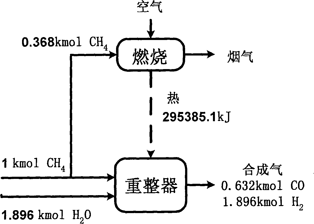
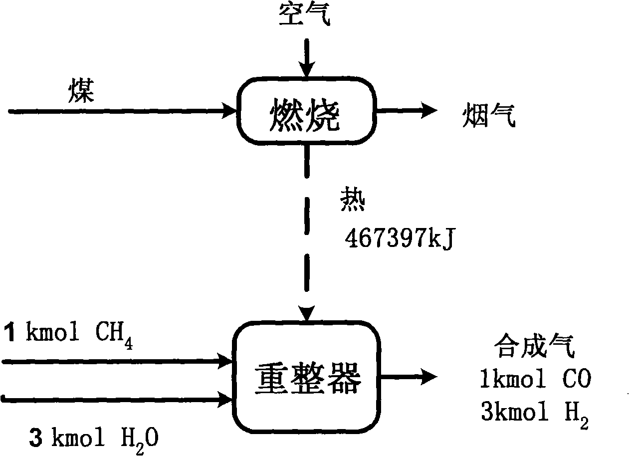
[0063] Among them, the reforming reactor 11 is used to prepare hydrogen and carbon monoxide synthesis gas from coal and natural gas, and output the prepared synthesis gas to the shift reactor 12 after being cooled. The...


PUM


Abstract

The invention discloses a multifunctional energy system. In the system, coal and natural gases simultaneously enter a reforming reactor, and the coal fires in the reforming reactor to drive the reforming reaction of natural gases, which generates synthetic gases of H2 and CO; the synthetic gases pass through a shift converter to convert CO into CO2, and then enter a pressure swing adsorption device(PSA) for preparing hydrogen gases; tail gases generated in the PSA device are sent to a CO2 separator to separate out a majority of CO2, and then compressed and cooled to become liquid CO2, which is convenient for transportation and storage; hydrogen rich fuel gases remained after the separation of CO2 are sent to a generating set, and high-temperature flue gases enter a waste heat recovery and a steam generation device, and the flue gases, the waste heat of which is recovered, are discharged in air; the flue gases discharged by a dual fuel reformer are also enter the waste heat recovery and steam generation device for recovering the waste heat, and then enter the CO2 separator to separate CO2 contained in flue gases; purified CO2 is compressed and liquefied, and finally the flue gases are discharged in air. The multifunctional energy system has the advantages of improving the utilization rate of the fuel and realizing the control and recovery of CO2 with zero energy consumption.

Description

technical field [0001] The present invention relates to hydrogen production, power generation and CO 2 In the field of emission control technology, it particularly relates to a multifunctional energy system that uses coal and natural gas as fuel to prepare hydrogen and liquid carbon dioxide and realize power generation. Background technique [0002] The technologies related to the present invention mainly include hydrogen production technology, power generation technology and CO 2 Control technologies, their respective technological developments and system features are as follows. [0003] 1. Hydrogen production technology [0004] Hydrogen is widely used in industrial processes, such as petroleum, chemical industry, metallurgy, aerospace, medicine, etc., among which the petrochemical industry is the most widely used. There are many types of hydrogen production processes in industry. According to different raw materials, they can be divided into hydrogen production from f...

Claims


Application Information

Patent Timeline
IPC IPC(8): C10J1/00C10K3/00C01B3/02F02C6/00F01K27/00F01D15/10
CPCY02P20/129
Inventor 金红光韩巍高林
Owner 中科思道(南京)储能技术有限公司
Why Eureka
Try Eureka