Repel push magnetic body component, complete permanent magnetism complete suspending bearing as well as combined wind power photovoltaic power generation system

A magnet assembly, permanent magnet technology, applied in photovoltaic power generation, wind power generation, magnetic bearings, etc., can solve the problems of discontinuous power generation, support vibration, low efficiency of wind power generation system, etc., to reduce vibration, eliminate friction, and reduce start-up The effect of wind speed

Inactive Publication Date: 2008-11-12
李国坤 +1
View PDF2 Cites 30 Cited by
  • Summary
  • Abstract
  • Description
  • Claims
  • Application Information

AI Technical Summary

Problems solved by technology

[0006] The invention solves the problems of low efficiency, discontinuous power generation, and vibrations to supports in the existing single-machine small and medium-power wind power generation system, and provides a repulsion magnet assembly for a vertical shaft, using the full permanent magnet o...

Method used


Image

  • Repel push magnetic body component, complete permanent magnetism complete suspending bearing as well as combined wind power photovoltaic power generation system
  • Repel push magnetic body component, complete permanent magnetism complete suspending bearing as well as combined wind power photovoltaic power generation system
  • Repel push magnetic body component, complete permanent magnetism complete suspending bearing as well as combined wind power photovoltaic power generation system

Examples


Embodiment Construction

[0034] The present invention will be further described below in conjunction with the accompanying drawings.

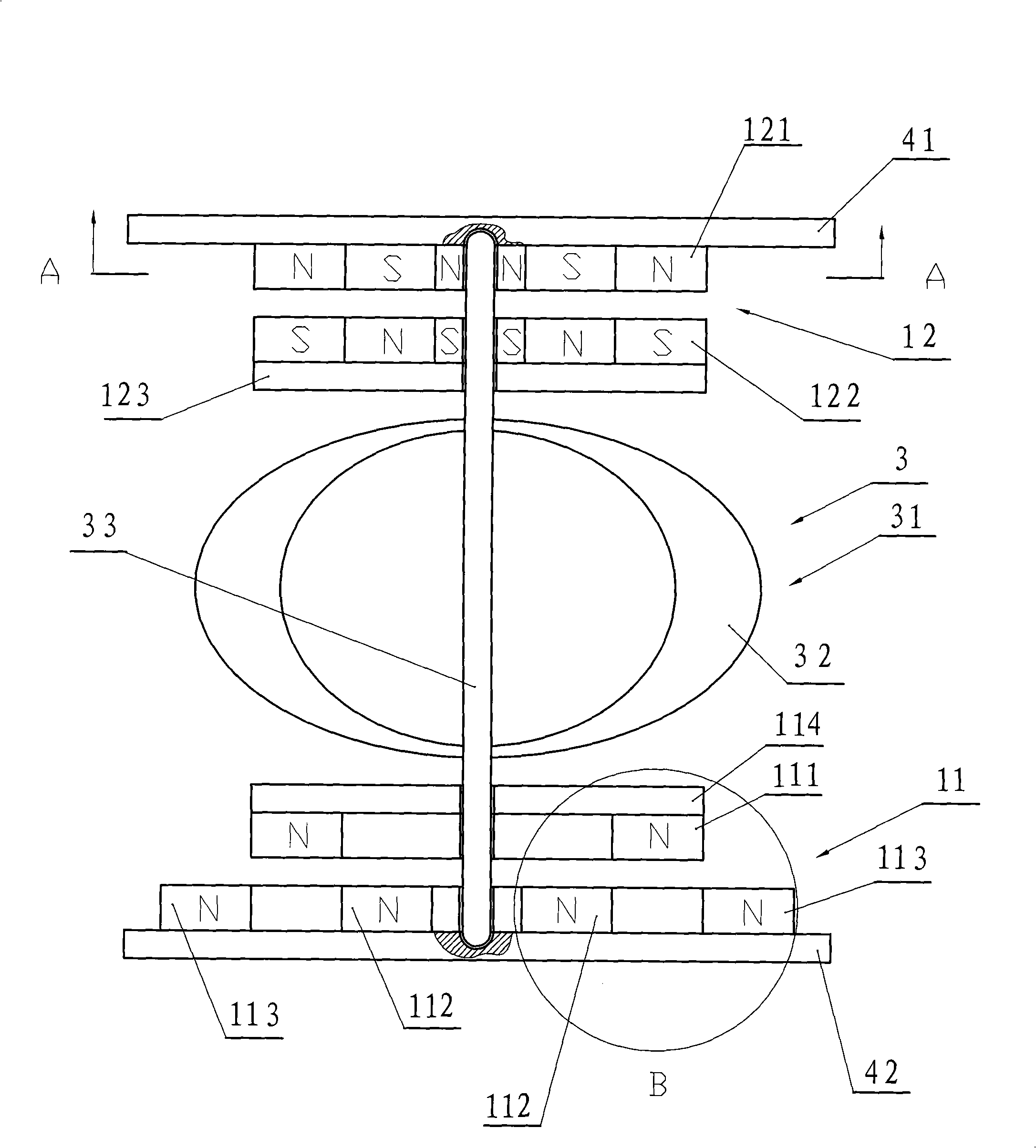
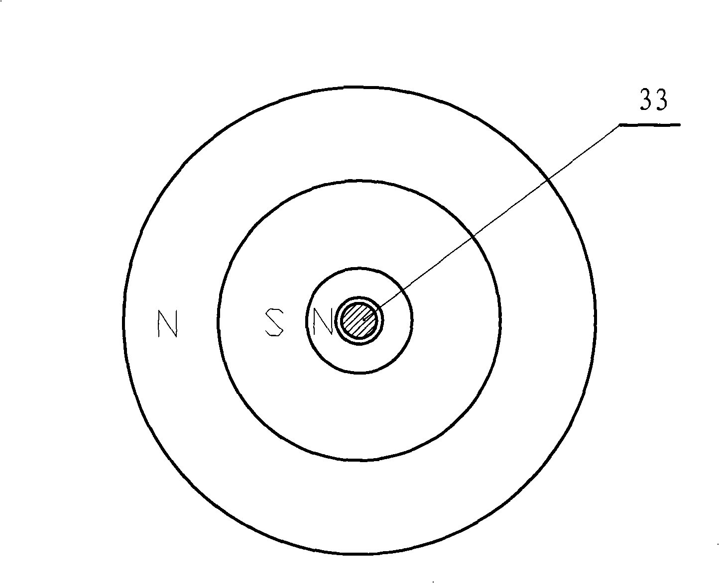
[0035] figure 1 The vertical shaft wind power generator is provided with a full permanent magnet full suspension bearing composed of a repelling magnet assembly 11 and a pull-push magnet assembly 12. Column 43 ( figure 1 Not shown in the middle), the fixed bracket, the generator 2 ( figure 1 not shown) or the generator 2 ( figure 1 Not shown), the wind turbine 3 includes a vertical shaft rotating body 31, the rotating body 31 of this embodiment is composed of a vertical shaft impeller 32 and a main shaft 33, and can also be other forms of rotating body, such as a rotating body that only includes a vertical shaft type impeller 32 .

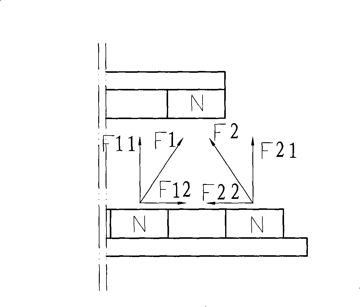
[0036] Wherein the repulsion magnet assembly 11 is arranged on the vertical main shaft 33, including the coaxial center with the main shaft 33, the repulsion upper body and the repulsion lower body arranged at a certain distance up and ...


PUM


Abstract

The invention relates to 'repulsive magnetic component, full permanent magnetic and full suspending bearing and compound wind power photovoltaic power system', in particular to a magnetic bearing and a wind power system, wherein, the repulsive magnetic component is arranged on a vertical main shaft. The invention is characterized in that the wind power system comprises an upper repulsive body and a lower repulsive body which are formed by homopolar ring permanent magnets; the upper repulsive body is formed by a piece of hollow ring permanent magnet while the lower repulsive body is formed by a piece of inner ring permanent magnet and a piece of outer ring permanent magnet arranged in a certain radial distance from the inner ring permanent magnet; the hollow ring permanent magnet is positioned in the effective magnetic range of the magnetic force of the two pieces of permanent magnets forming the lower repulsive body. By adopting the full permanent and full suspending bearing of the repulsive magnetic component, and arranging a pull-push magnet component at the upper end of a spiral body of a vertical shaft wind turbine and the repulsive magnetic component at the lower end of the spiral body, the full magnetic and full suspending support of the main shaft or a vertical shaft impeller can be realized, thus eliminating all friction of the spiral body of the wind turbine.

Description

Technical field: [0001] The invention relates to a renewable energy utilization device, in particular to a full-permanent-magnet full-suspension bearing using a repelling magnet assembly, a wind power generator and a combined wind-power photovoltaic power generation system using the bearing. Background technique: [0002] Wind energy is a clean natural resource that comes from a wide variety of sources. Using wind energy to generate electricity has the characteristics of no pollution and low maintenance costs. Wind power has become one of the world's important energy sources and development directions. However, due to reasons such as mechanical friction and mechanical momentum, the starting wind speed has become the main bottleneck restricting the scope and timing of wind energy resource utilization. A large number of low-speed wind energy resources cannot be utilized. Due to the instability of wind energy resources, the efficiency of wind turbines is often insufficient. ...

Claims


Application Information

Patent Timeline
IPC IPC(8): F16C32/04F03D9/00F03D3/00F03D3/06F03D3/04H02K7/18H02N6/00F03D9/25F03D80/70H02S10/12
CPCF16C39/063Y02E10/74F16C32/0408F16C2360/31Y02E10/50Y02E10/72
Inventor 李国坤闻淑英
Owner 李国坤
Why Eureka
Try Eureka