Process and equipment for preparing biological energy source

A technology of bio-energy and equipment, which is applied in the fields of bio-energy manufacturing equipment, cultivation of photosynthetic organisms and waste gas treatment, to achieve the effect of reducing regeneration links, improving utilization rate, reducing energy consumption and equipment investment and operation costs

Inactive Publication Date: 2008-11-19
朱洪
View PDF0 Cites 8 Cited by
  • Summary
  • Abstract
  • Description
  • Claims
  • Application Information

AI Technical Summary

Problems solved by technology

Contents of

Method used


Image

  • Process and equipment for preparing biological energy source
  • Process and equipment for preparing biological energy source
  • Process and equipment for preparing biological energy source

Examples


Embodiment 1

[0064] Embodiment 1 The patented technology is illustrated by taking the absorption of liquid ammonia as an example below:

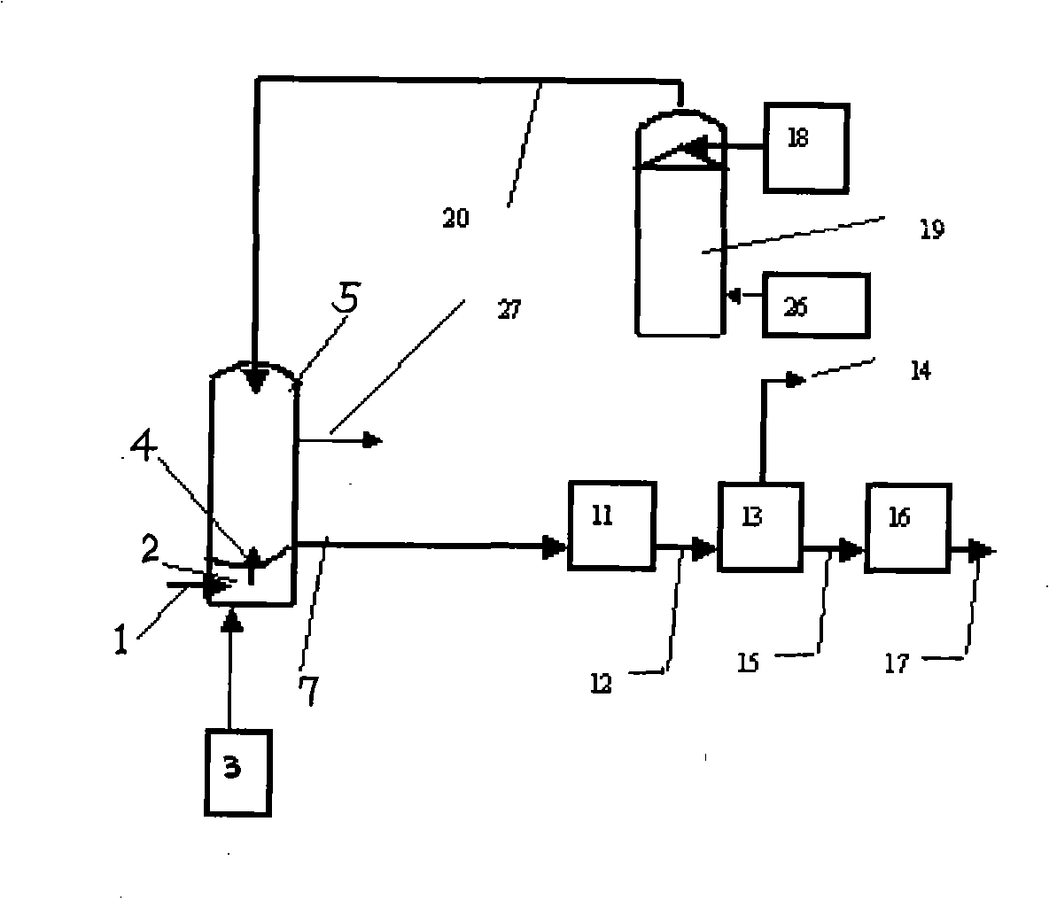
[0065] The absorption separation agent or absorption separation agent precursor storage tower 18 sends the absorption separation agent or absorption separation agent precursor such as urea to the spray tower 19 after heating 26 to produce absorption separation agent 30 such as liquid ammonia. The absorption separation agent 30 such as liquid ammonia enters the absorption / separation device through the absorption separation agent supply pipe 20 .

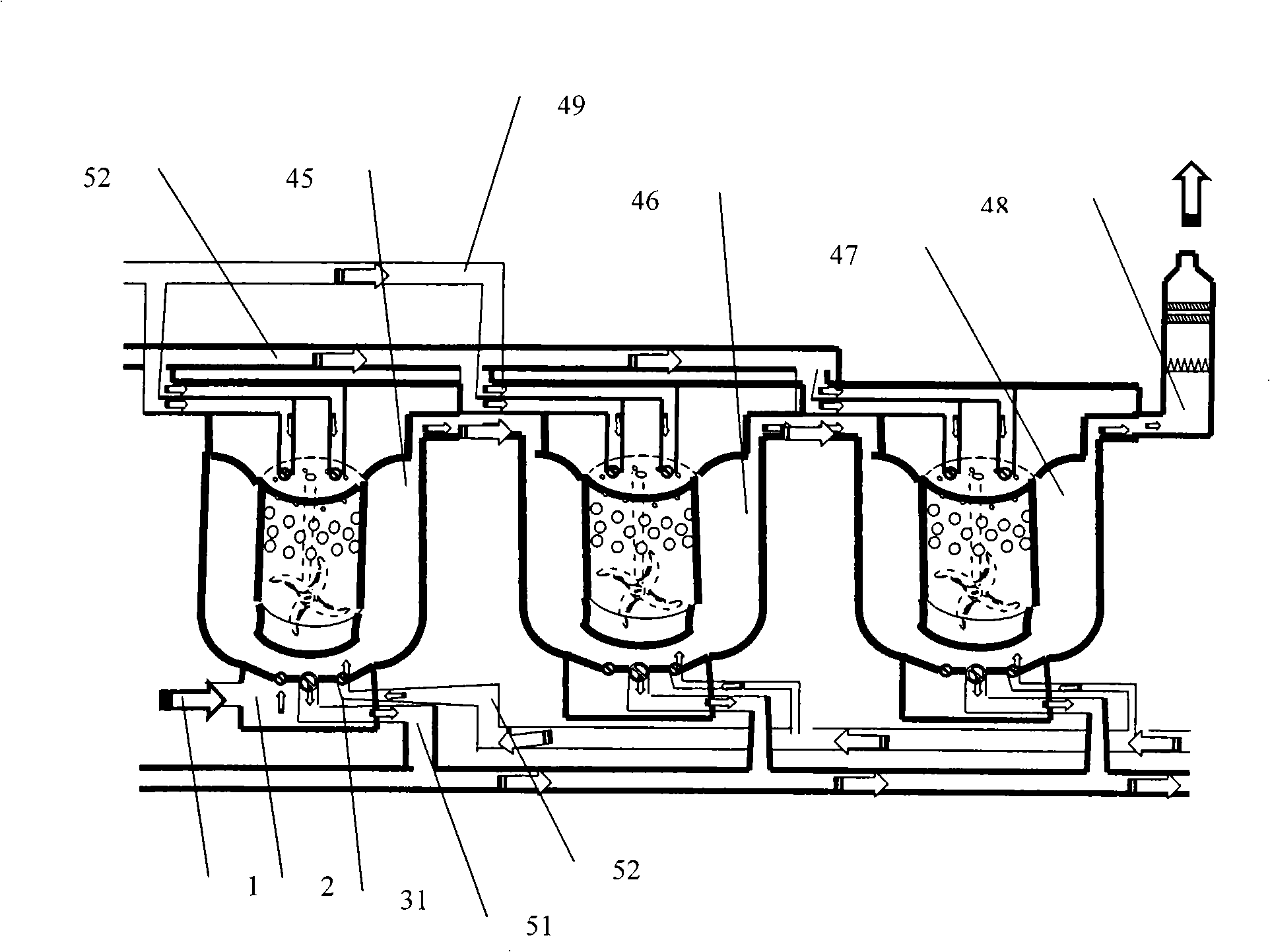
[0066] due to CO 2 Reacting with liquid ammonia can form solid sediment, which is easy to block the absorption pipe. This patent provides absorption / separation equipment designed with multi-blade radial impellers (the shaded part represents the blade part), which rotates at a speed of 1400rpm, and there is a thick hole with a large wall outside. The net (33) is detachably fixed on the upper wall of the absorber...

Embodiment 2

[0070] Hereinafter, the present invention will be further described by taking the combination of absorption separation agent liquid ammonia absorption and gas separation membrane as an example.

[0071] The absorption separation agent or absorption separation agent precursor storage tower 18 sends the absorption separation agent or absorption separation agent precursor such as urea to the spray tower 19 after heating 26 to produce absorption separation agent 30 such as liquid ammonia. The absorption separation agent 30 such as liquid ammonia enters the absorption / separation device through the absorption separation agent supply pipe 20 .

[0072] due to CO 2 Reacting with liquid ammonia can form solid sediment, which is easy to block the absorption pipe. This patent provides absorption / separation equipment designed with multi-blade radial impellers (the shaded part represents the blade part), which rotates at a speed of 1400rpm, and there is a thick hole with a large wall outsi...


PUM


Abstract

The invention relates to a method for preparing a biological energy source and a device for carrying out the same. Carbon element captured through absorption/separation is used for cultivating microalgae in a form of a liquid carbon containing compound. And simultaneously components which are contained in exhaust air and pollute the atmosphere are eliminated. In the prior art for capturing carbon, after CO2 is absorbed/separated, the carbon is regenerated in a form of CO2 and is compressed and canned for storage, transportation and reconversion. The invention saves a CO2 regenerating link to a certain degree, thereby saving a CO2 micropore pipe link and a CO2 compression, canning, storage and transportation link accounting for 1/3 of the total microalgae cultivation cost, and consequently reducing operating cost and improving the carbon utilization ratio of microalgae when cultivating microalgae. The device comprises three parts, namely an absorption/separation device, a biological cultivation vessel and a conversion device for biological cultivation products. When CO2 is captured, dusty gases such as oxysulfide, nitric oxide, sour gas (HCl), fluoride (HF), etc. are also captured from the exhaust air.

Description

technical field [0001] The invention relates to equipment and methods for bioenergy production. The invention relates to equipment and methods for cultivating photosynthetic organisms and waste gas treatment. This invention involves waste gas carbon capture, wastewater treatment, chemical industry, pharmaceuticals, paper making, nutritional additives and food manufacturing. Background technique [0002] Large-scale cultivation of photosynthetic organisms such as microalgae for biomass energy production, high-protein grain production, pharmaceuticals, and waste gas and wastewater treatment has attracted widespread attention. Achieving high yields and low cost of outdoor photosynthetic organisms such as microalgae is the key to establishing profitable commercial production. [0003] The existing microalgae cultivation methods mainly use microporous pipelines to transfer CO 2 It is blown into the culture medium in gaseous form so that the microalgae can absorb it. CO 2 The...

Claims


Application Information

Patent Timeline
IPC IPC(8): C12M1/00C12N1/12B01D53/75B01D53/84
CPCC12M43/00
Inventor 朱洪
Owner 朱洪
Why Eureka
Try Eureka