Supercharge Your Innovation With Domain-Expert AI Agents!

Metal-based composite material containing both micro-sized carbon fiber and nano-sized carbon fiber

A composite material and nano-sized technology, which is applied in thin material processing, transportation and packaging, circuits, etc., can solve the problems of molten copper and poor wettability of nanofibers, and achieve the effect of light weight

Inactive Publication Date: 2008-12-10
岛根县
View PDF3 Cites 19 Cited by
  • Summary
  • Abstract
  • Description
  • Claims
  • Application Information

AI Technical Summary

Problems solved by technology

In particular, none of the above-mentioned documents makes the matrix contain nanofibers. In the methods disclosed in these documents, it is difficult to disperse nanofibers in metals (reaction of nanofibers, molten aluminum and molten magnesium, wettability of molten copper and nanofibers) bad unadulterated

Method used


Image

  • Metal-based composite material containing both micro-sized carbon fiber and nano-sized carbon fiber
  • Metal-based composite material containing both micro-sized carbon fiber and nano-sized carbon fiber
  • Metal-based composite material containing both micro-sized carbon fiber and nano-sized carbon fiber

Examples


Embodiment 1

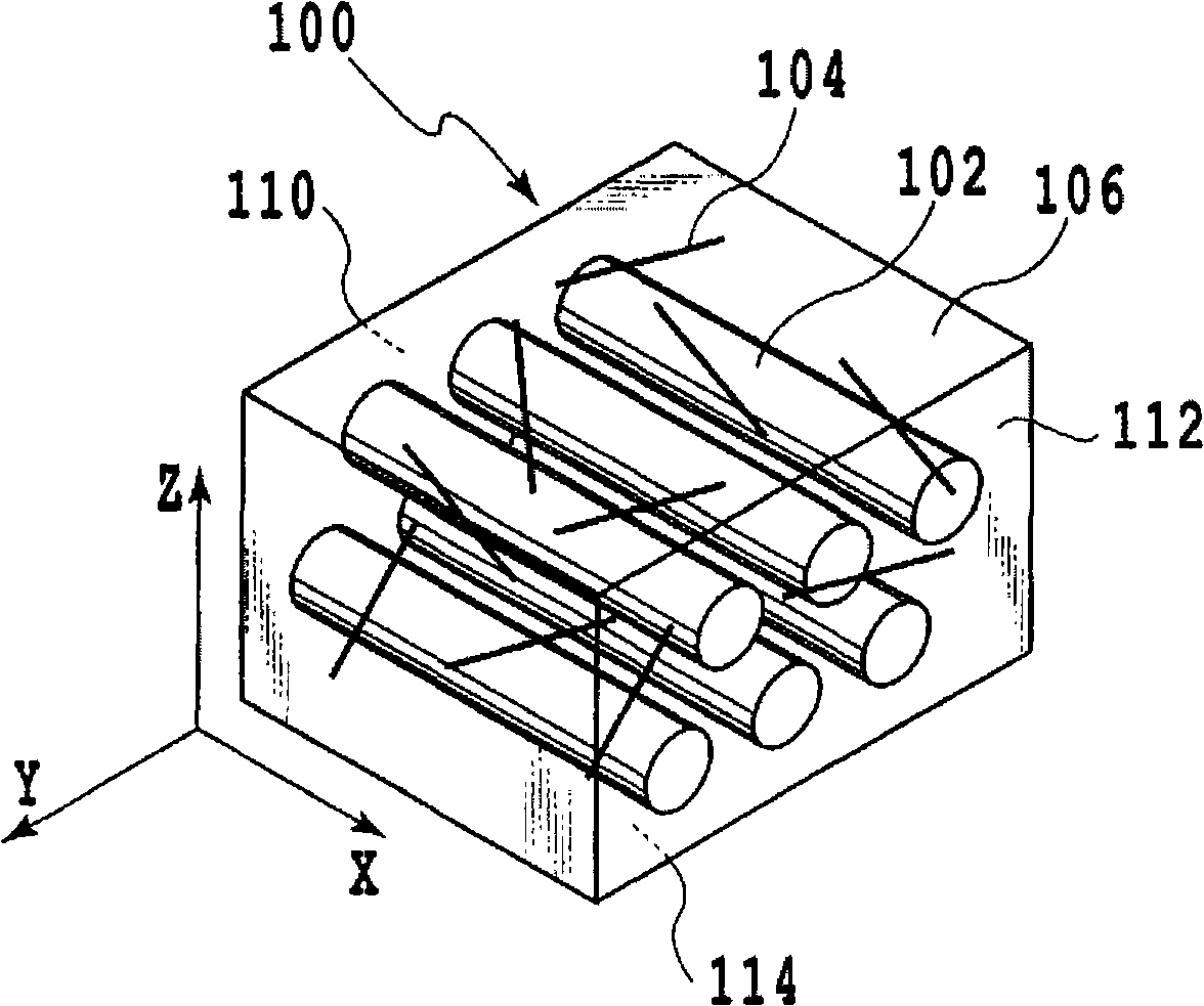
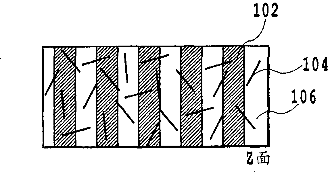
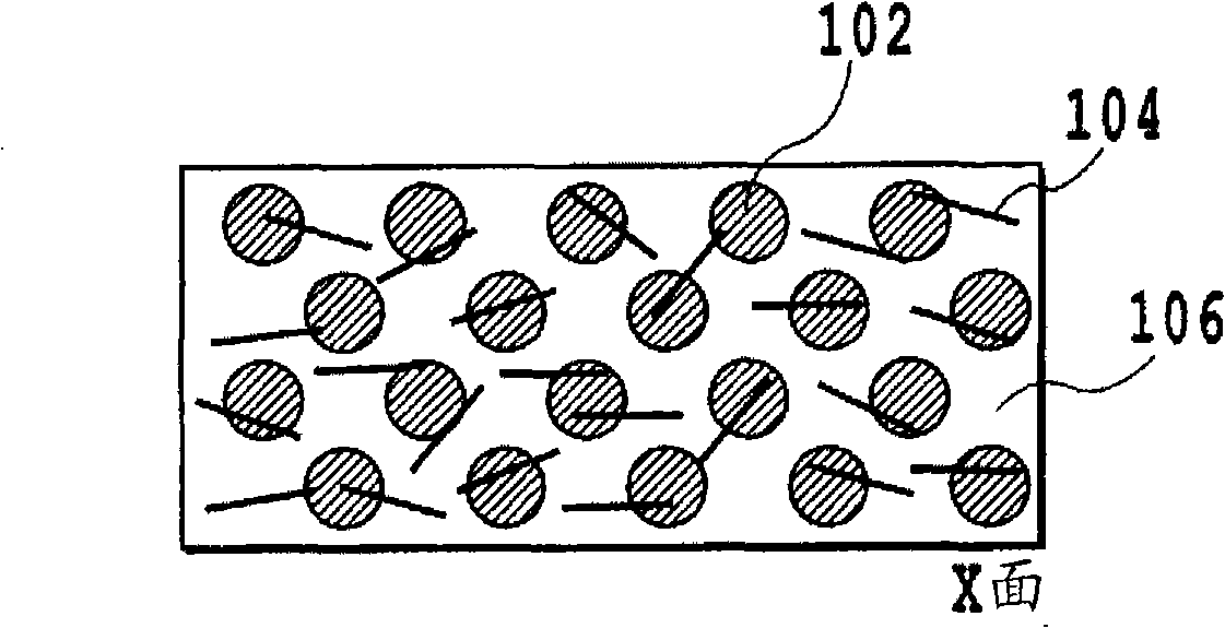
[0126] An example of an aluminum-vapor-grown carbon fiber nanofiber-pitch-based carbon fiber composite material is shown.

[0127] Aluminum powder (manufactured by Showa Denko: average particle size 5 μm), vapor-grown carbon fiber nanofibers (hereinafter VGCF, manufactured by Showa Denko: diameter 150 nm, aspect ratio 60 or more), pitch-based carbon fiber (diameter 10 μm, 2000 fiber bundles) were used.

[0128] 80 cc of isopropanol was added to 47.5 g of aluminum powder and 2.5 g of VGCF, and mixed with an ultrasonic mixing device for 1 hour to obtain an aluminum-nanofiber mixture.

[0129] The fiber bundle of pitch-based carbon fiber is immersed in the suspension obtained as described above, and the aluminum-nanofiber mixture is adhered to the fiber bundle.

[0130] Dry by air drying for 24 hours. As a result, a metal powder-nano-sized carbon fiber attached fiber composed of 33.3% by weight of aluminum powder, 1.7% by weight of VGCF, and 65% by weight of pitch-based carbon fibers...

Embodiment 2

[0137] An example of an aluminum-vapor-grown carbon fiber nanofiber composite material is shown.

[0138] Aluminum powder (manufactured by Showa Denko: average particle size 5 μm), vapor-grown carbon fiber nanofibers (hereinafter VGCF, manufactured by Showa Denko: diameter 150 nm, aspect ratio 60 or more), pitch-based carbon fiber (diameter 10 μm, 2000 fiber bundles) were used.

[0139] 80 cc of isopropanol was added to 42.5 g of aluminum powder and 7.5 g of VGCF, and mixed with an ultrasonic mixing device for 1 hour.

[0140] Dry by air drying for 24 hours. As a result, a mixed powder of 75% by weight of aluminum powder and 15% by weight of VGCF was obtained.

[0141] This mixed powder was filled in a graphite sintering mold having a 20 mm square cross section. The mold was sintered using a pulse current sintering machine in a vacuum of 10 Pa, a pressure of 50 MPa, and a sintering temperature of 600° C. to obtain a composite material. Table 3 shows the thermophysical properties o...

Embodiment 3

[0146] Each of the composite materials obtained in the foregoing Examples 1 and 2 was filled in a graphite sintering mold having a 20 mm square cross section. A pulse energization sintering machine was used to sinter the mold in a vacuum of 10 Pa, a pressure of 50 MPa, and a sintering temperature of 600° C. to obtain a composite material with no micron-sized carbon fibers in the surface area. The composite material is a composite material in which each layer has the characteristics obtained in Examples 1 and 2 above.


PUM

PropertyMeasurementUnit
diameteraaaaaaaaaa
particle diameteraaaaaaaaaa

Abstract

Disclosed is a metal-based carbon fiber composite material improved in thermal expansion rate and thermal conductivity and having light weight. The composite material comprises a metal and carbon fibers comprising micron carbon fibers and nanofiber and has a first surface. The micron carbon fibers are oriented in a direction parallel to the first surface and run from one end to the other end continuously. 80% of the nanofibers are oriented at an angle within 30 DEG with respect to the first surface. In the surface parallel to the first surface, the nanofibers are oriented randomly. In the surface area of the composite material, the micron carbon fibers may be present in a less amount than that in other area or no carbon fiber may be present. In the composite material, the nanofibers may be oriented in a direction parallel to the surface of the composite material. Also disclosed is a method for production of the composite material.

Description

Technical field [0001] The invention relates to a metal-based carbon fiber composite material. More specifically, it relates to a metal matrix composite material containing both micron-sized and nano-sized carbon fibers and a method of manufacturing the same. Background technique [0002] In recent years, the heat generation of electronic equipment, including semiconductor devices, is on the way to increase. Taking the PC CPU as an example, the power consumption has doubled in the past 5 years (Furukawa Electric Times No. 106, http: / / www.furukawa.co.jp / jiho / fj106 / fj106_01.pdf (not Patent Document 1)), along with this, the amount of heat generation also increases. [0003] As a countermeasure for heat dissipation of such electronic equipment, there is generally a method of using a heat dissipation device such as a heat sink. When a heat sink is used for cooling, the thermophysical properties of the material for the heat sink will have a large impact on the cooling performance. [...

Claims


Application Information

Patent Timeline
Patent Type & Authority Applications(China)
IPC IPC(8): C22C49/14C22C47/04C22C47/14C22C49/02C22C49/04C22C49/06C22C101/10
CPCB22F2998/00C22C26/00C22C47/14C22C49/04C22C49/14C22C2026/002H01L23/373H01L23/3736H01L2924/0002Y10T428/24124Y10T428/24942B22F2207/01C22C47/025H01L2924/00C22C47/04
Inventor 上野敏之
Owner 岛根县
Features
  • R&D
  • Intellectual Property
  • Life Sciences
  • Materials
  • Tech Scout
  • Unparalleled Data Quality
  • Higher Quality Content
  • 60% Fewer Hallucinations
Learn More