Catalytic conversion method and special apparatus therefor

A catalytic conversion method and special device technology, which is applied in the field of catalytic conversion method and its special device, can solve the problems of regeneration heat release that cannot provide heat, process technology economic discount, increase equipment and energy consumption, etc., to achieve convenience and heat shortage , Solve the heat shortage and make up for the effect of less heating capacity

Active Publication Date: 2008-12-17
石宝珍
View PDF3 Cites 20 Cited by
  • Summary
  • Abstract
  • Description
  • Claims
  • Application Information

AI Technical Summary

Problems solved by technology

Although in order to increase the production of low-carbon olefins, 5-8% additives can be added to the regenerator to further convert small molecules, but when the additives are added to the FCC catalyst, due to the dilution of the catalyst, the cracking activity of the catalyst will inevitably decrease.
Usually, for every 5% additives added, the cracking conversion rate of heavy oil decreases by 1 percentage point, and the reduction of conversion rate of heavy oil is an important factor that seriously affects the technical economy of FCC. At the same time, the concentration of additives is very low after mixing with heavy oil cracking catalyst , the improvement of the target product is limited
[0012] 2. Since the second reaction system requires more heat of reaction, coke is generally less, and the heat released by the regeneration of coke itself cannot provide the heat required for the reaction. If the original technology is used to establish an independent second reaction system, it will be restricted by heat balance problems
After the process of first cooling down and then heating up, the investment in equipment and energy consumption is increased, which greatly reduces the economical efficiency of the process technology

Method used


Image

  • Catalytic conversion method and special apparatus therefor
  • Catalytic conversion method and special apparatus therefor
  • Catalytic conversion method and special apparatus therefor

Examples


Embodiment 1

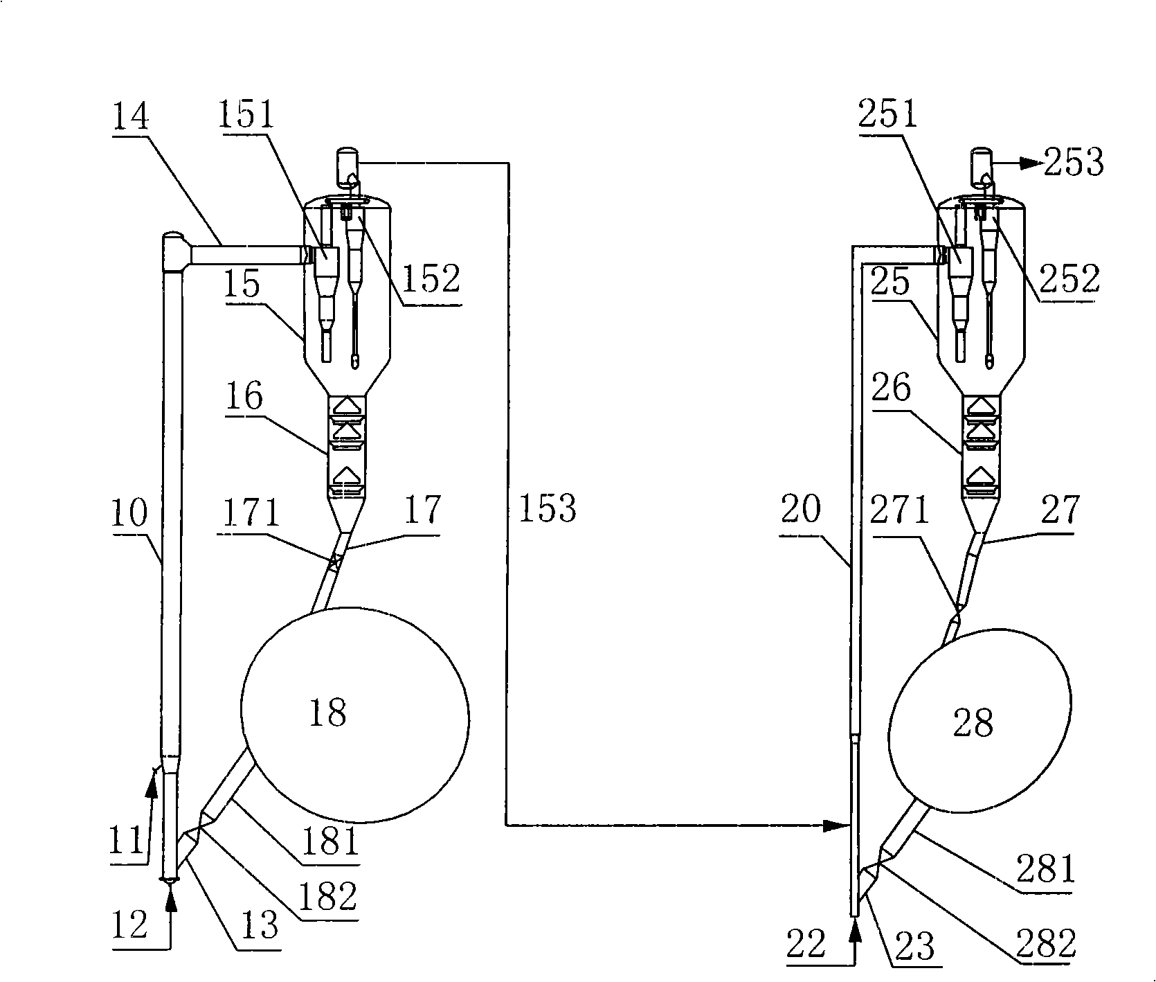
[0042] The method of this embodiment is as figure 1 As shown, it consists of two parts, the first reaction system and the second reaction system; the first reaction system includes a first reactor 10, a settler 15, a stripping section 16 and a catalyst regenerator 18; the first reactor 10 is a riser , the bottom end is provided with a regenerated catalyst inlet 13, the stripping section 16 receives the raw standpipe 17, the waiting slide valve 171, the regenerator 18 is connected with the regeneration standpipe 181, and the regeneration slide valve 182; a first-stage gas-solid separator is arranged in the settler 15 151, secondary gas-solid separator 152; the second reaction system includes a second riser reactor 20, a settler 25, a stripping section 26 and a regenerator 28; the bottom of the second riser reactor 20 is provided with a regenerated catalyst inlet 23, The stripping section 26 receives the raw standpipe 27, the raw slide valve 271, the regenerator 28 is connected ...

Embodiment 2

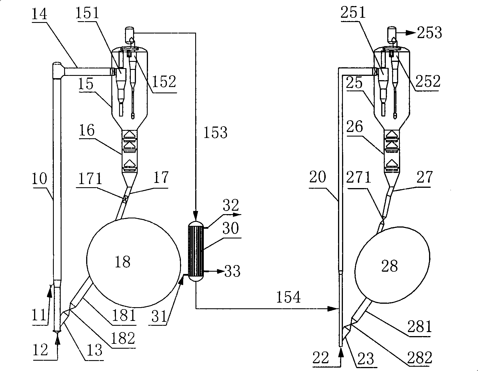
[0049] The method of this embodiment is as figure 2 As shown, the vertical heat exchange device exchanges heat. A vertical heat exchange device 30 is installed between the two reaction systems. The reaction oil gas 153 from the first reaction system enters the heat exchange device 30, and the cooling temperature is 350°C. After heat exchange and cooling, the part with a boiling point greater than 350°C becomes liquid phase 33 and discharged Part of the reaction oil gas 154 with a boiling point less than 350° C. enters the pre-lift section of the second riser reactor 20 in a gas phase state. 31 and 32 are heat exchange mediums.

[0050] The first reaction system is mainly used for decarburization and demetallization. The reaction conditions are: the reaction temperature is 485°C, the reaction time is 1.5s, the reaction pressure is 0.30MPa(A), and the regeneration temperature is 680°C. The reaction temperature of the second reaction system is 535°C, the reaction time is 2.5s,...

Embodiment 3

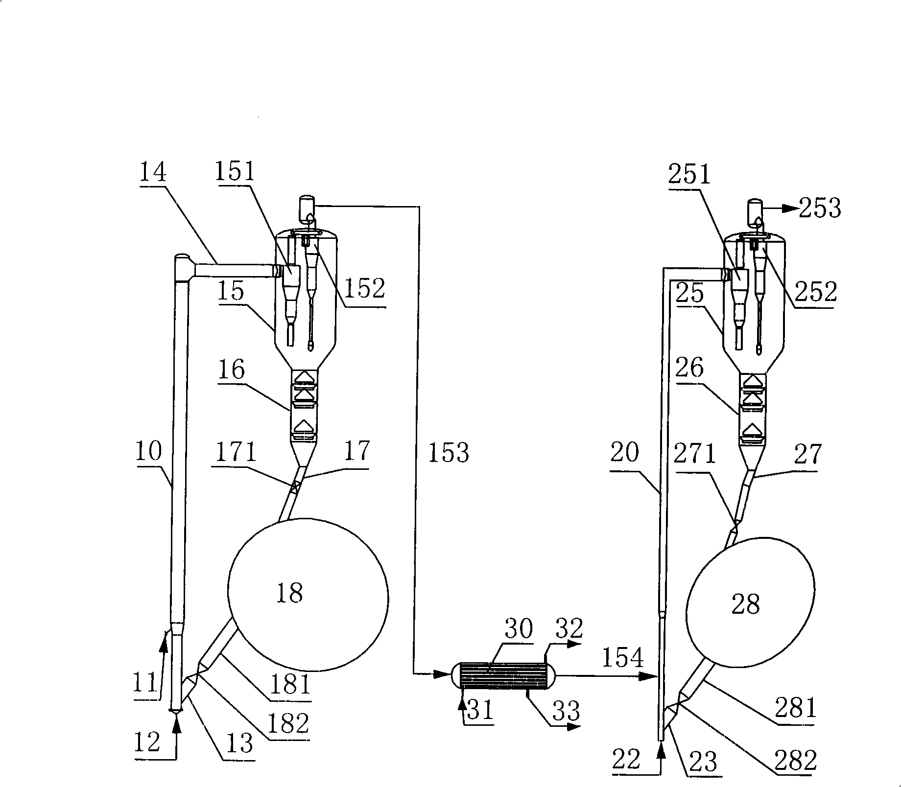
[0053] The method of this embodiment is as image 3 As shown, a horizontal heat exchange device is provided for heat exchange. A horizontal heat exchange device 30 is installed between the two reaction systems. The reaction oil gas 153 from the first reaction system enters the heat exchange device 30, 31 and 32 are heat exchange media, and the cooling temperature is 280°C. After heat exchange and cooling, the boiling point is greater than 280°C The part becomes the liquid phase 33 and is discharged, and the part with a boiling point less than 280° C., that is, the heat exchange reaction oil gas 154 enters the pre-lift section of the second riser reactor 20 in a gas phase state.

[0054] The reaction temperature of the second reactor is 600°C, and the reaction time is 2.0s. Others are the same as embodiment 2.

[0055] The properties and product distribution of raw oil are shown in Table 1.


PUM


Abstract

The invention discloses a catalytic conversion method which belongs to the technical field of catalytic conversion of petrolic alkanes. The catalytic conversion is carried out in a first reaction system and a second reaction system sequentially; after raw oil enters the first reaction system for catalytic reaction, all or part of the produced fractions enter the second reaction system in gaseous state and/or liquid state for further catalytic reaction; the first reaction system and the second reaction system respectively use a corresponding catalyst according to different reaction raw materials and target products. By using two reaction systems, the method of the invention using pertinence catalysts to carry out selective catalytic conversion of different fractions, overcomes the deficiencies of poor selectivity and low adjuvant content, and diluting the catalyst when adopting single catalyst, can enhance the productivity of chemical raw materials such as low carbon alkene, etc. and enhance the yield of products; the method overcomes the shortcoming of large energy consumption for cooling and preheating and saves investment, thus greatly enhancing the economical efficiency.

Description

(1) Technical field [0001] The invention belongs to the technical field of catalytic conversion of petroleum hydrocarbons, in particular to a catalytic conversion method and a special device thereof. (2) Background technology [0002] Catalytic conversion is the most important process in the secondary processing of crude oil. Petroleum hydrocarbon raw materials (including atmospheric heavy oil, vacuum oil press, vacuum wax oil, coking wax oil, etc.) are catalytically converted in a catalytic conversion device to form gasoline, diesel, Liquefied petroleum gas and other products. [0003] Low-carbon olefins represented by ethylene and propylene are the most basic raw materials in the chemical industry. The existing catalytic conversion technology is to produce low-carbon olefins while producing gasoline and diesel, which is far from meeting the current market demand for organic chemical raw materials. Aromatics is an important organic chemical raw material second only to ethy...

Claims


Application Information

Patent Timeline
Patent Type & Authority Applications(China)
IPC IPC(8): C10G57/00C10G7/02
Inventor 石宝珍
Owner 石宝珍
Why Eureka
Try Eureka