Method and system for cleaning boiler tube

A technology for cleaning systems and furnace tubes, applied in cleaning methods and utensils, cleaning methods using liquids, chemical instruments and methods, etc., can solve the problems of weak removal ability of metal ions and organic polymer particles, failure to achieve cleaning effect, etc. Achieve good furnace tube cleaning effect, better cleaning effect, and better cleaning effect

Inactive Publication Date: 2008-12-24
SEMICON MFG INT (SHANGHAI) CORP
View PDF1 Cites 32 Cited by
  • Summary
  • Abstract
  • Description
  • Claims
  • Application Information

AI Technical Summary

Problems solved by technology

This method has a good removal effect on metals, especially alkali metal ions, such as potassium and sodium ions, but its removal ability on other metal ions and organic polymer particles is relatively weak, especially for large diameter and complex structures. Furnace tube, can not achieve a good cleaning effect

Method used


Image

  • Method and system for cleaning boiler tube
  • Method and system for cleaning boiler tube

Examples


Embodiment Construction

[0024] In order to make the above objects, features and advantages of the present invention more clearly understood, the preferred embodiments of the present invention will be described in detail below with reference to the accompanying drawings.

[0025] In the following description, numerous specific details are set forth in order to provide a thorough understanding of the present invention. However, the present invention can be implemented in many other ways different from those described herein, and those skilled in the art can make similar promotions without departing from the connotation of the present invention. Accordingly, the present invention is not limited by the specific implementations disclosed below.

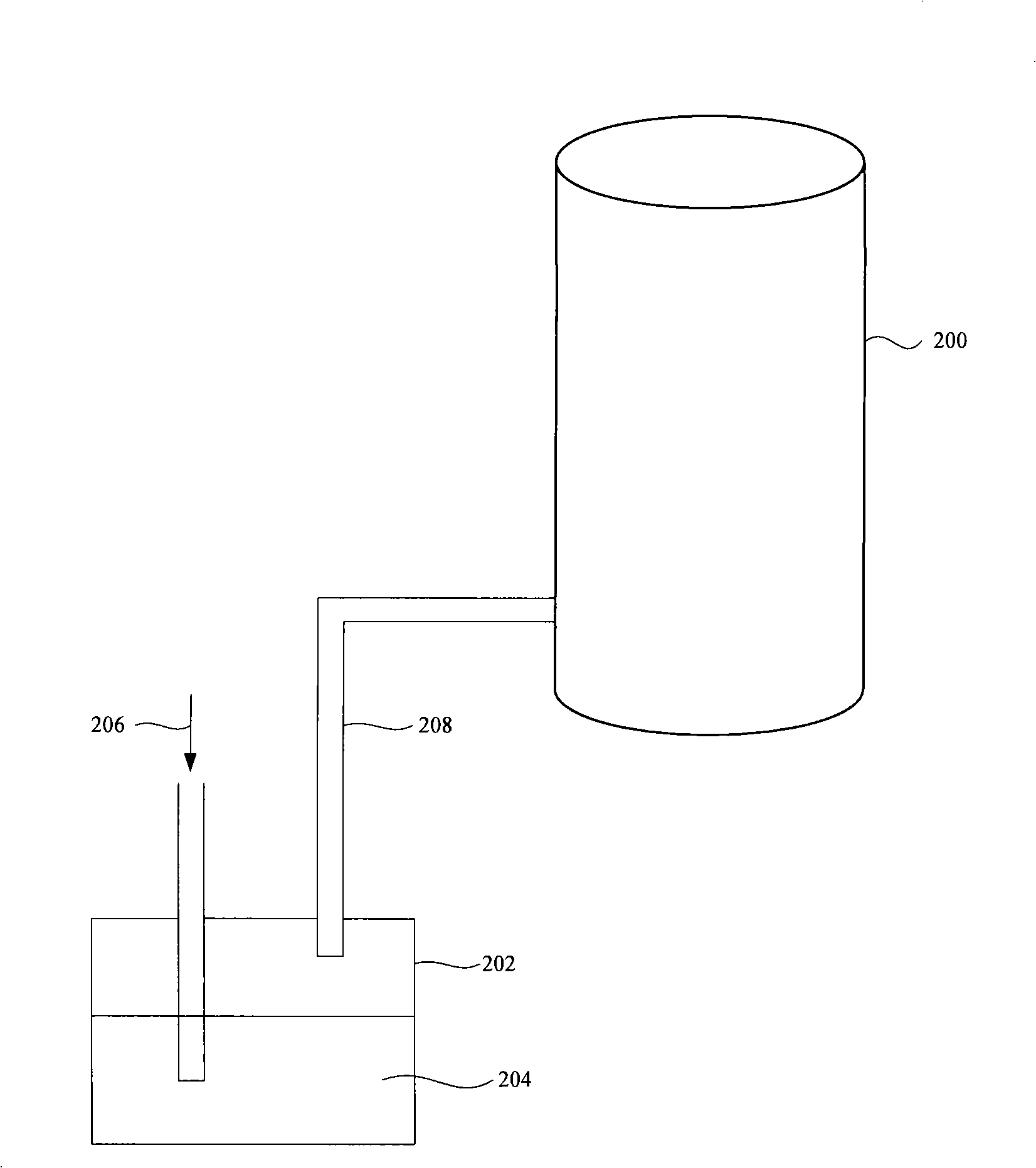
[0026] figure 2 It is a schematic diagram of a furnace tube cleaning method and device according to an embodiment of the present invention. The furnace tube equipment used in the furnace tube thermal oxidation process generally has various forms such as horizo...


PUM


Abstract

The invention discloses a furnace tube cleaning system and method. Nitrogen gas enters into a cleaning agent tank, wherein, the cleaning agent carried by the nitrogen gas enters into the furnace tube via a pipeline to clean the furnace tube; hydrogen and oxygen are mixed to produce water vapor which enters into the furnace tube to clean the furnace tube. The furnace tube cleaning method of the invention is capable of effectively removing the metallic and non-metallic impurity sediments inside the furnace tubes in the semiconductor calcar pipes.

Description

technical field [0001] The invention relates to the technical field of semiconductor manufacturing, in particular to a furnace tube cleaning method and system for thermal oxidation furnace tube (Oxidation Furnace) equipment. Background technique [0002] The semiconductor manufacturing process is mainly to perform multiple photolithography processes, etching processes and film forming processes, etc., and stack semiconductor elements with special structures on the surface of the semiconductor wafer. Among them, a thermal oxidation method and a chemical vapor deposition (CVD) process are generally used in the film forming process for forming various thin films. Among them, the thermal oxidation method is mainly the furnace tube thermal oxidation method. After the reaction gas is introduced into the high temperature furnace tube, the reaction gas and the semiconductor wafer in the furnace are chemically reacted, and a thin film is deposited on the surface of the wafer. This p...

Claims


Application Information

Patent Timeline
Patent Type & Authority Applications(China)
IPC IPC(8): B08B9/027B08B7/00
CPCB08B3/04B08B9/00B08B9/08C23C16/4405F27B17/0025F27D7/02F27D17/004
Inventor 赵星宋海李春龙陈晓丽
Owner SEMICON MFG INT (SHANGHAI) CORP
Why Eureka
Try Eureka