
Heat treating furnace using porous medium combustor

A technology for heat treatment furnaces and porous media, applied in the direction of burners, gas fuel burners, combustion methods, etc., can solve the problems of high manufacturing, installation and transformation costs, complex structures, and large burner volumes, and achieve low manufacturing costs. Small size, energy saving effect

Inactive Publication Date: 2009-01-07
NORTHEASTERN UNIV
View PDF0 Cites 2 Cited by
  • Summary
  • Abstract
  • Description
  • Claims
  • Application Information

AI Technical Summary

Problems solved by technology

[0005] In addition, the traditional burner has a large volume and a relatively complicated structure, and the cost of manufacturing, installation and transformation is relatively high

Method used


Image

  • Heat treating furnace using porous medium combustor
  • Heat treating furnace using porous medium combustor
  • Heat treating furnace using porous medium combustor

Examples


Embodiment Construction

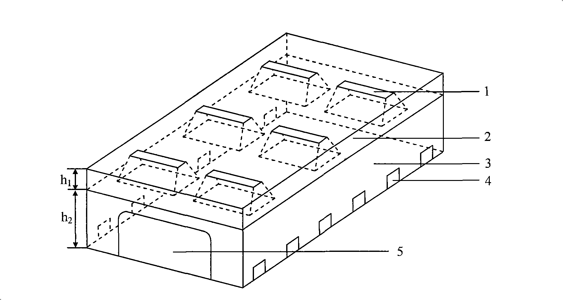
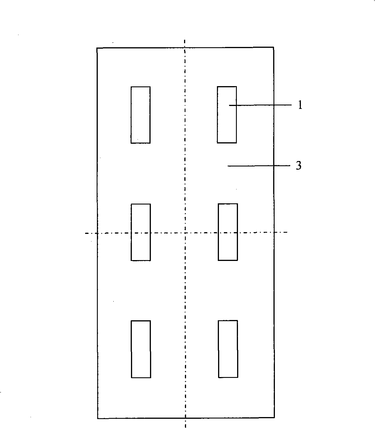
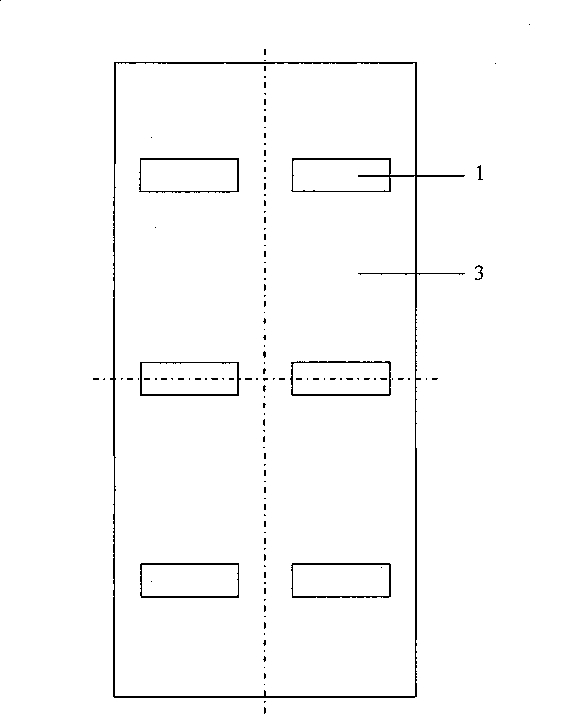
[0034] Taking a porous media burner with a rectangular outlet section as an example, the specific implementation of a heat treatment furnace using a porous ceramic foam burner is described. Such as figure 1 As shown, the hearth 3 of the heat treatment furnace is a cuboid structure, and the front of the hearth 3 is equipped with a furnace door 5, 2 is the furnace roof, and the porous medium burner 1 is arranged on the furnace roof 2. Its radiation output share is more characteristic. The refractory masonry with the outlet section of the burner facing down is designed as a trumpet shape that gradually widens from top to bottom. The line of intersection between the extension surface and the furnace wall is located above the workpiece to be heated. The flue gas outlet 4 is arranged on both side walls of the furnace 3, and the bottom of the flue gas outlet 4 is flush with the bottom of the furnace. figure 2 , 3 Two arrangements of porous media burners 1 with rectangular outlet ...


PUM

PropertyMeasurementUnit
porosityaaaaaaaaaa
porosityaaaaaaaaaa

Abstract

A heat processing furnace which adopts a porous medium burner belongs to the technical field of heat processing furnace. The furnace includes a hearth body and burners. The burners adopt porous ceramics foam; the burners are arranged on the top part or the side wall of the furnace; the surrounding masonrys of the outlet sections of the burners are designed to be of a gradually expanded horn shape; the crossing line of the extending surface of the outlet sections of two neighboring burners or the crossing line between the extending surface of the outlet sections of the burners and the wall of the furnace wall is arranged above a workpiece to be heated; the heat loss of the wall of the furnace arranged in the mode is less; the radiation heat transmission share is large. The ceramics materials of the burners are cordierite, yttrium oxide-based zirconia, calcium oxide-based zirconia, silicon nitride, aluminum oxide or the ceramics particles bonded by a bonding agent. The burner is formed by one or a plurality of same burning units. The porous medium burner of the invention has the advantages of small size, low manufacture cost, low mounting difficulty, large adjusting ratio, high burning intensity and low contamination discharge. The heat processing furnace has the advantages of high burning efficiency, less heat loss and high heating quality.

Description

technical field [0001] The invention belongs to the technical field of heat treatment furnaces, and relates to an industrial heat treatment furnace, in particular to a heat treatment furnace using a porous medium burner. Background technique [0002] The heat treatment furnace is the basic equipment in the heat treatment workshop of metallurgical factories and machinery manufacturing plants. It is the last process in the process of metallurgy and machining. So far, heat treatment furnaces generally use traditional burners, and the combustion method is mainly diffusion combustion or premixed combustion. The combustion process is completed in the free space of the furnace, and the combustion heat analysis is mainly transmitted to the workpiece by the flame or high-temperature flue gas through radiation and convection; the heat directly transmitted to the workpiece by flame radiation only accounts for a few percent, and most of the radiated heat reaches the furnace wall first....

Claims


Application Information

Patent Timeline
Patent Type & Authority Applications(China)
IPC IPC(8): C21D1/00F23D14/12F27D23/00F27D99/00
Inventor 李本文田溪岩董帅王慧玲许学成饶文涛
Owner NORTHEASTERN UNIV
Learn More