Flat type brushless electric pump and electric water pump group for vehicle using the same

A brushless motor, flat type technology, applied in electric components, components of pumping devices for elastic fluids, synchronous motors with stationary armatures and rotating magnets, etc., can solve unsolvable space waste, fluid retention , Increase the number of shielding sleeve parts, etc., to achieve the effect of improving the characteristics of the motor, extending the friction coefficient, and reducing the axial dimension

Inactive Publication Date: 2009-01-07
YAMAMOTO ELECTRIC
View PDF1 Cites 6 Cited by
  • Summary
  • Abstract
  • Description
  • Claims
  • Application Information

AI Technical Summary

Problems solved by technology

[0006] However, in the above-mentioned conventional technology, although the rotor can be arranged in the pump casing, it is necessary to arrange the stator core and winding outside the pump casing, and to supply power to the stator, and to hold / hold the stator. The surrounding structure still has problems in terms of miniaturization and placement
In addition, since the electric motor has a cylindrical shape that is long in the axial direction of the rotor, it cannot solve the problem of wasted space in the engine room of the vehicle.
[0007] In addition, although the above-mentioned conventional technology has a structure in which the rotor is arranged in the pump casing, the structure of the bearing part has not been realized, so there is a concern that the fluid may stagnate near the bearing.
In addition, the casing is extended in the axial direction of the rotor, so the fluid cannot smoothly detour (flow) from the pump suction port to the discharge port.
In addition, since the rotor is relatively long in the axial direction, the resistance of the fluid to the rotor group composed of the rotor shaft, the sleeve, and the rotor magnet is large, so there is a need for a large-sized motor or a motor with a large power consumption. question
In addition, when constituting an electric pump, the watertightness of the bearing part needs to be considered. In this case, a large amount of work is required to complete the sealing structure, and there are problems such as liquid leakage from the sealing part and bearing failure.
[0008] In addition, there is also a conventional example in which a conductive part such as a stator is liquid-tightly surrounded by a shield casing (CAN) made of a non-magnetic material, such as a CANNED MOTOR PUMP. In this case, Not only the number of parts of the shielding case (CAN) increases, but also there are problems such as insufficient cooling of heat-generating parts such as armature coils and switching elements

Method used


Image

  • Flat type brushless electric pump and electric water pump group for vehicle using the same
  • Flat type brushless electric pump and electric water pump group for vehicle using the same
  • Flat type brushless electric pump and electric water pump group for vehicle using the same

Examples


Embodiment

[0051] Hereinafter, embodiments of the present invention will be described based on the drawings.

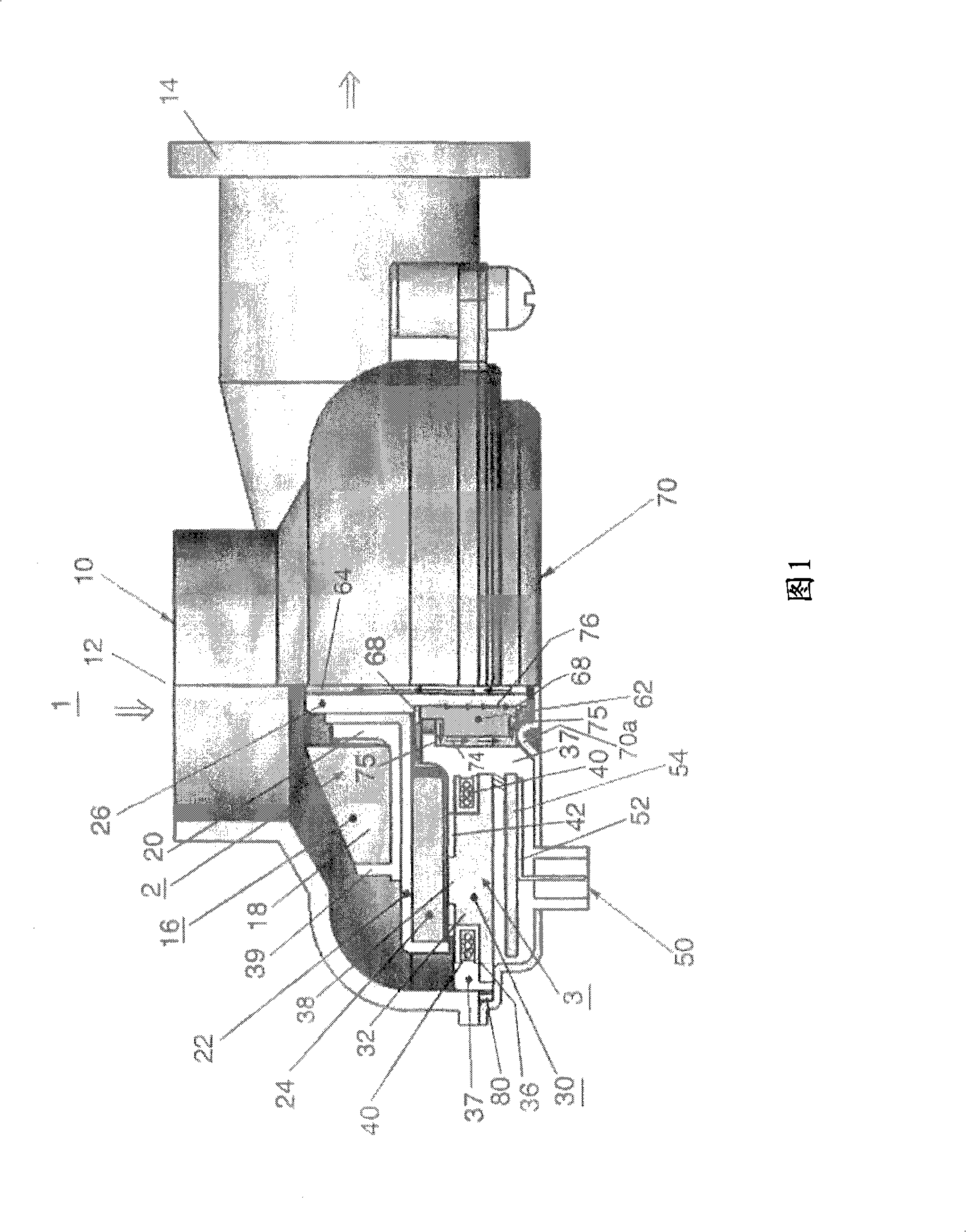
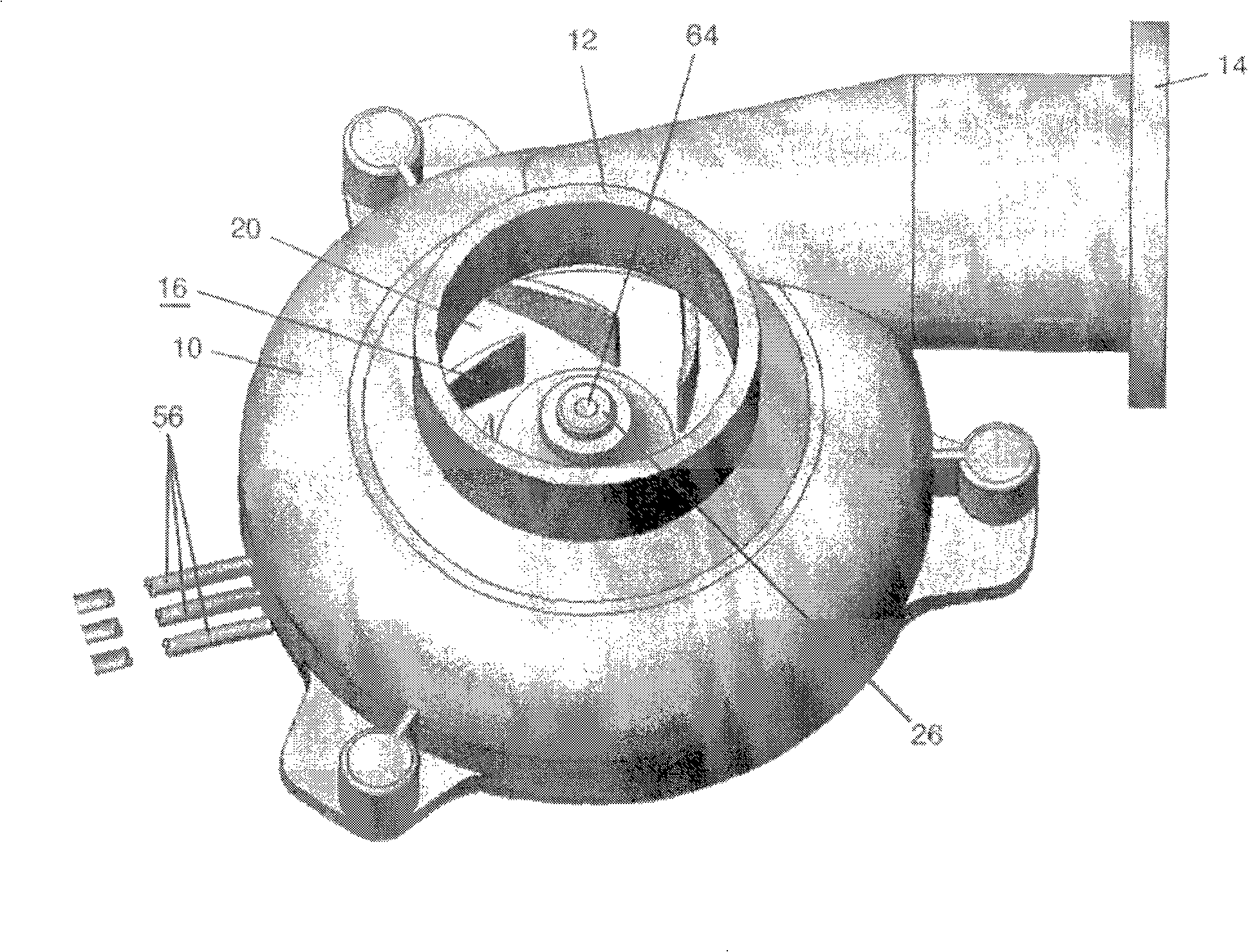
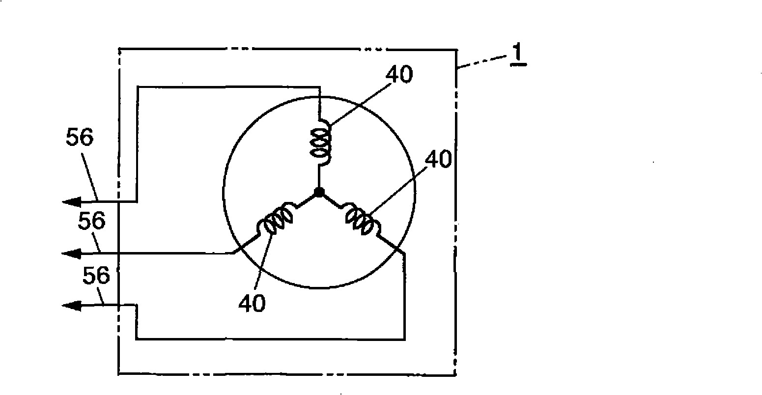
[0052] Fig. 1 is a partial sectional view showing the side of an embodiment of the brushless electric pump of the present invention and its partial internal structure, Figure 2A is the three-dimensional view of its appearance, Figure 2B is its equivalent circuit diagram.

[0053] Reference numeral 10 in FIG. 1 is the housing (pump body) of the brushless electric pump 1, and 12 and 14 are respectively the suction port of the fluid and the discharge port of the fluid provided on the housing 10. By rotating the impeller (blade) 16, The fluid is sucked from the suction port 12 and detoured (flowed) toward the discharge port 14 to be discharged from the discharge port 14 . The impeller 16 is formed by arranging a plurality of plates 18 radially on a bushing 20 , and is fixed to a motor rotor (rotor) yoke 22 to rotate integrally with the rotor yoke 22 .

[0054] The impeller 16 is...


PUM


Abstract

A flat brushless motor pump comprising a flat brushless motor, an impeller coupled with the rotating shaft of the flat brushless motor, a pump casing for containing the flat brushless motor and the impeller and having a suction opening for sucking fluid and a delivery opening for delivering fluid, and a motor cover constituting a part of the pump casing and holding the bearing of the flat brushless motor which bears the rotating shaft rotatably wherein the fluid is sucked from the suction opening by the rotation of the rotting shaft and delivered from the delivery opening.; The flat brushless motor comprises a stator section having a core around which a plurality of armature coils are wound and a terminal connected electrically with the armature coils and formed by resin molding the core and the terminal watertightly, and a rotor section formed of a magnet arranged oppositely to the core through an air gap, the rotating shaft and a yoke secured to the rotating shaft and holding the magnet, wherein the bearing is an underwater bearing for sliding the rotating shaft by a water membrane.

Description

technical field [0001] The present invention relates to a fluid pump, in particular, a flat brushless electric pump suitable for use in a liquid cooling device such as a radiator for an internal combustion engine of a vehicle, and an electric water pump unit for a vehicle using the flat brushless electric pump. Background technique [0002] Conventionally, a liquid-cooled pump for an internal combustion engine mounted on a vehicle is often operated by transmitting the rotation of a pulley attached to the engine shaft to the pump through a belt. Since this type of pump is driven by a belt, the installation position is naturally limited to the vicinity of the engine, so the degree of freedom in the installation position is small, resulting in useless space in the engine room. In addition, when the engine rotates at a high speed and generates more unnecessary flow than necessary, or when the engine is stopped while the coolant temperature is high, the engine oil, etc. will dete...

Claims


Application Information

Patent Timeline
Patent Type & Authority Applications(China)
IPC IPC(8): F04D13/06F04D29/046H02K21/24
CPCH02K7/14F04D29/0473F04D29/0413H02K21/24F04D29/063F04D29/047F04D13/0666
Inventor 吉田浩柳沼真一
Owner YAMAMOTO ELECTRIC
Why Eureka
Try Eureka