
Active phase array antenna electrical property prediction method based on mechanical, electric and thermal three-field coupling

A phased array antenna and electrical performance technology, which is applied in the field of antennas to achieve the effects of reducing development costs and shortening development cycles

Active Publication Date: 2009-01-14
XIAN CETC XIDIAN UNIV RADAR TECH COLLABORATIVE INNOVATION INST CO LTD
View PDF0 Cites 40 Cited by
  • Summary
  • Abstract
  • Description
  • Claims
  • Application Information

AI Technical Summary

Problems solved by technology

[0009] The purpose of the present invention is to often ignore the coupling relationship between mechanical displacement field, thermal field and electromagnetic field in the existing active phased array antenna analysis technology, and consider the influence of one aspect separately, cause active phased array antenna structure and Electromechanical and thermal separation in thermal design, a method for predicting the electrical performance of planar active phased array antennas based on electromechanical and thermal three-field coupling is proposed to realize the electrical performance prediction of active phased array antenna three-field coupling, which can guide its structure and thermal design

Method used


Image

  • Active phase array antenna electrical property prediction method based on mechanical, electric and thermal three-field coupling
  • Active phase array antenna electrical property prediction method based on mechanical, electric and thermal three-field coupling
  • Active phase array antenna electrical property prediction method based on mechanical, electric and thermal three-field coupling

Examples


Embodiment Construction

[0036] The present invention will be described in further detail below with reference to the accompanying drawings.

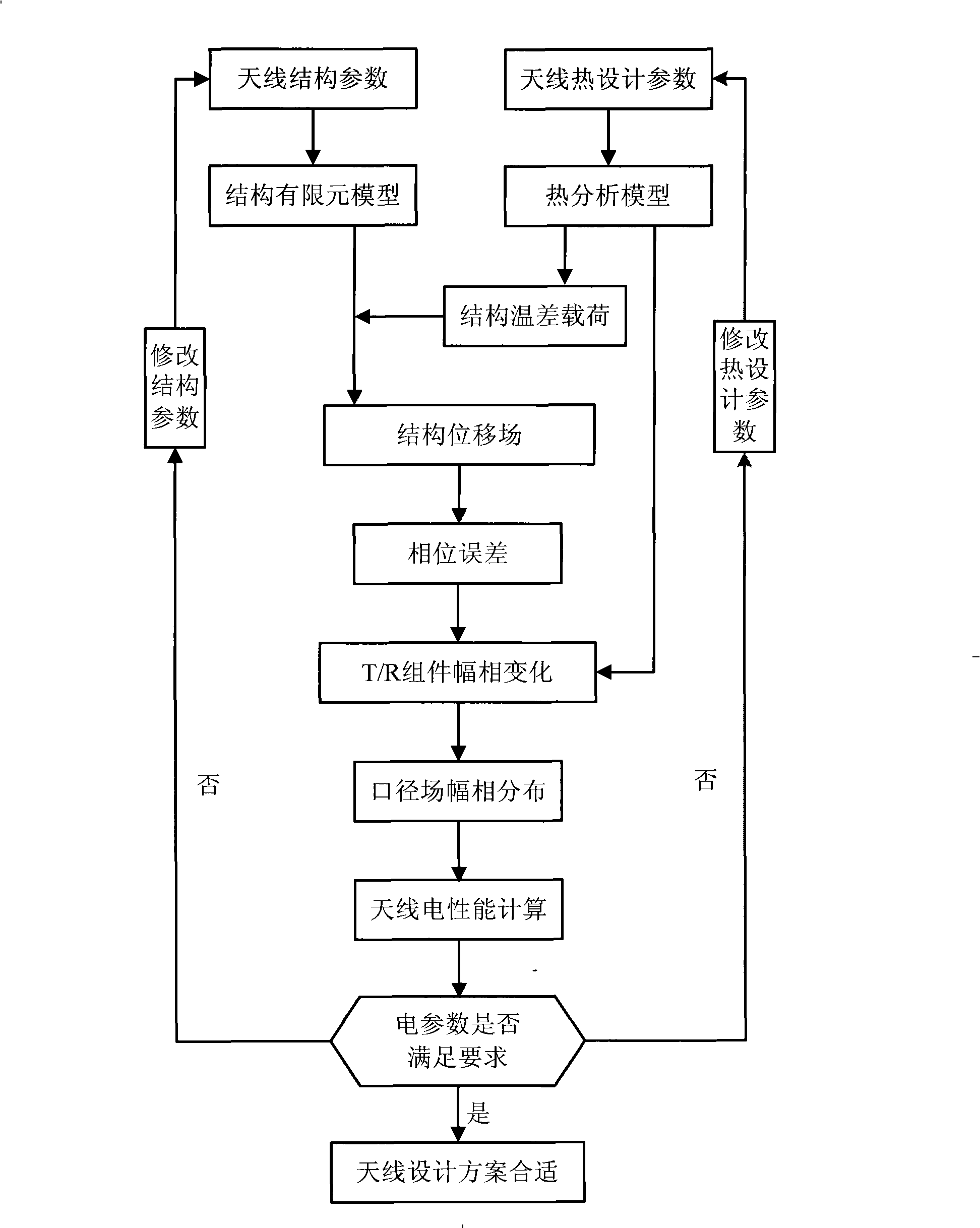
[0037] refer to figure 1 , the concrete steps of the present invention are as follows:

[0038] Step 1: Build the APAA structure model.

[0039] The APAA structural finite element model is determined by the structural parameters of the APAA's front shape, size, radiation element type, and antenna frame, such as Figure 9 shown. Theoretical coordinates (x, y, 0) of each radiation element on the front are obtained from the finite element model.

[0040] The second step is to establish the APAA thermal analysis model.

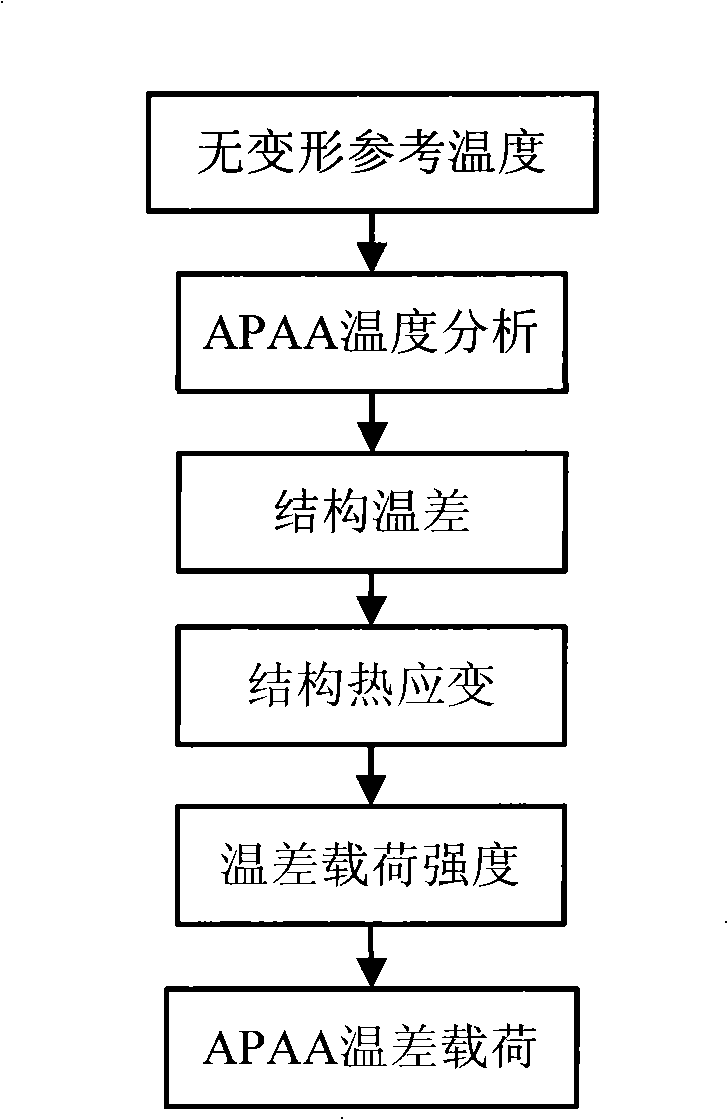
[0041] Use thermal analysis software to accurately establish the APAA thermal analysis model, which includes: structural material parameters, heat dissipation form, ambient reference temperature, T / R component thermal power, radiator size and physical parameters, air duct shape and size, and fan parameters . Due to the large number of APAA co...


PUM


Abstract

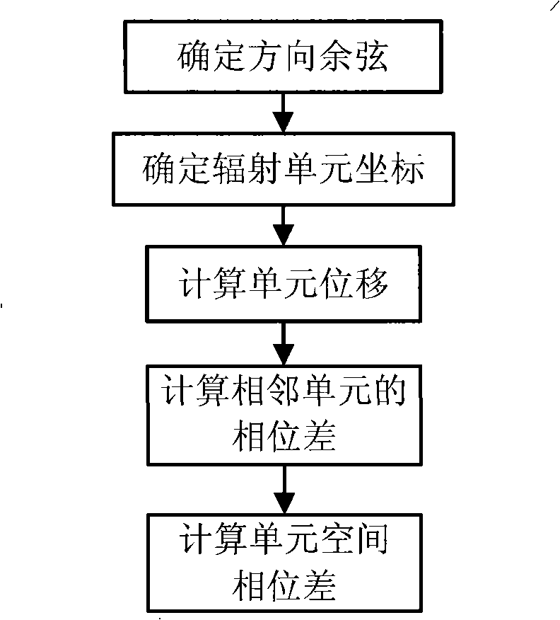
The invention discloses an electrical property pre-test method based on structure, electromagnet and heat, namely, three-field coupling and used for an active phased array antenna, mainly aiming at solving the problem about how to separate the mechanical part, electrical part and heating part in the structure and heat design for the active phased array antenna. The method includes the following steps: the structure and T / R component temperature are defined based on the structure and heat design parameters of the active phased array antenna; an antenna finite element analysis is carried out according to the result of a temperature difference load analysis to obtain a structure distortion under the antenna heat load and environment load and to analyze the phase difference of an antenna radiation unit; an amplitude phase error of T / R component exciting current is defined with the result of heat analysis; an antenna aperture field amplitude phase distribution can be obtained through the radiation unit phase difference and the exciting current amplitude phase error; an antenna far field direction graph is figured out in virtue of the aperture field distribution and array face irradiance function; then the antenna electrical property parameters can be obtained so as to realize the couple analysis on structure, electromagnet and heat of the active phased array antenna. The invention can be used for guiding the structure design and heat design and electrical property coupling analysis and evaluation of the active phased array antenna.

Description

technical field [0001] The invention belongs to the technical field of antennas, in particular to a method for predicting the electrical performance of a planar active phased array antenna, which is used to guide the structural design, thermal design, electrical performance simulation analysis and evaluation of the active phased array antenna. Background technique [0002] Phased array technology is a new technology being developed in recent years. It has a deeper and wider impact on the development of radar than any other technology such as monopulse and pulse Doppler. Active phased array antenna APAA technology can meet the requirements of high performance and high survivability at the same time, and it is also an important way to reduce the cost of radar development. The successful application of airborne active phased array radar (APAR) is a revolution to traditional airborne radar, which greatly expands the application field of radar and improves the working performance...

Claims


Application Information

Patent Timeline
IPC IPC(8): G01R31/00
Inventor 段宝岩王从思李鹏张福顺朱敏波郑飞保宏仇原鹰王伟冯昕罡高慧莲宋立伟
Owner XIAN CETC XIDIAN UNIV RADAR TECH COLLABORATIVE INNOVATION INST CO LTD
Learn More