Intervention type active speed limiting control device of motor vehicle

A control device and a technology for motor vehicles, which are applied in the field of interventional speed control devices for motor vehicles overspeeding, can solve the problems of increasing the complexity and difficulty of system monitoring, and cannot get rid of passive management and monitoring methods, and achieve easy implementation of technology and process manufacturing. , The social and economic benefits are obvious, and the effect of reducing the loss of life and property

Active Publication Date: 2009-01-14
李扬荣 +2
View PDF0 Cites 11 Cited by
  • Summary
  • Abstract
  • Description
  • Claims
  • Application Information

AI Technical Summary

Problems solved by technology

This "interval speed measurement" method seems to be fairer and more transparent than the "electronic eye" speed measurement point, but it still cannot get rid of the passive management and monitoring method with lagging technology, and the "interval speed measurement" involves many vehicles in the intervals involved in refueling, maintenance, and catering services The industry must incorporate parking meter management or reconstruction issues outside the interval, thus increasing the complexity and difficulty of system monitoring. At least, the parking time of vehicles in the interval will become the spare time for drivers to speed up at will when they get back on the road and lose the "interval." The real meaning of "speed measurement"
At present, except for a few special roads and special vehicles that can be directly tracked and monitored by satellites, there are no devices for active control and management of speeding vehicles on ordinary civil expressways.

Method used


Image

  • Intervention type active speed limiting control device of motor vehicle
  • Intervention type active speed limiting control device of motor vehicle
  • Intervention type active speed limiting control device of motor vehicle

Examples


Embodiment Construction

[0025] The present invention will be further described below in conjunction with the contents of the present invention and the accompanying drawings.

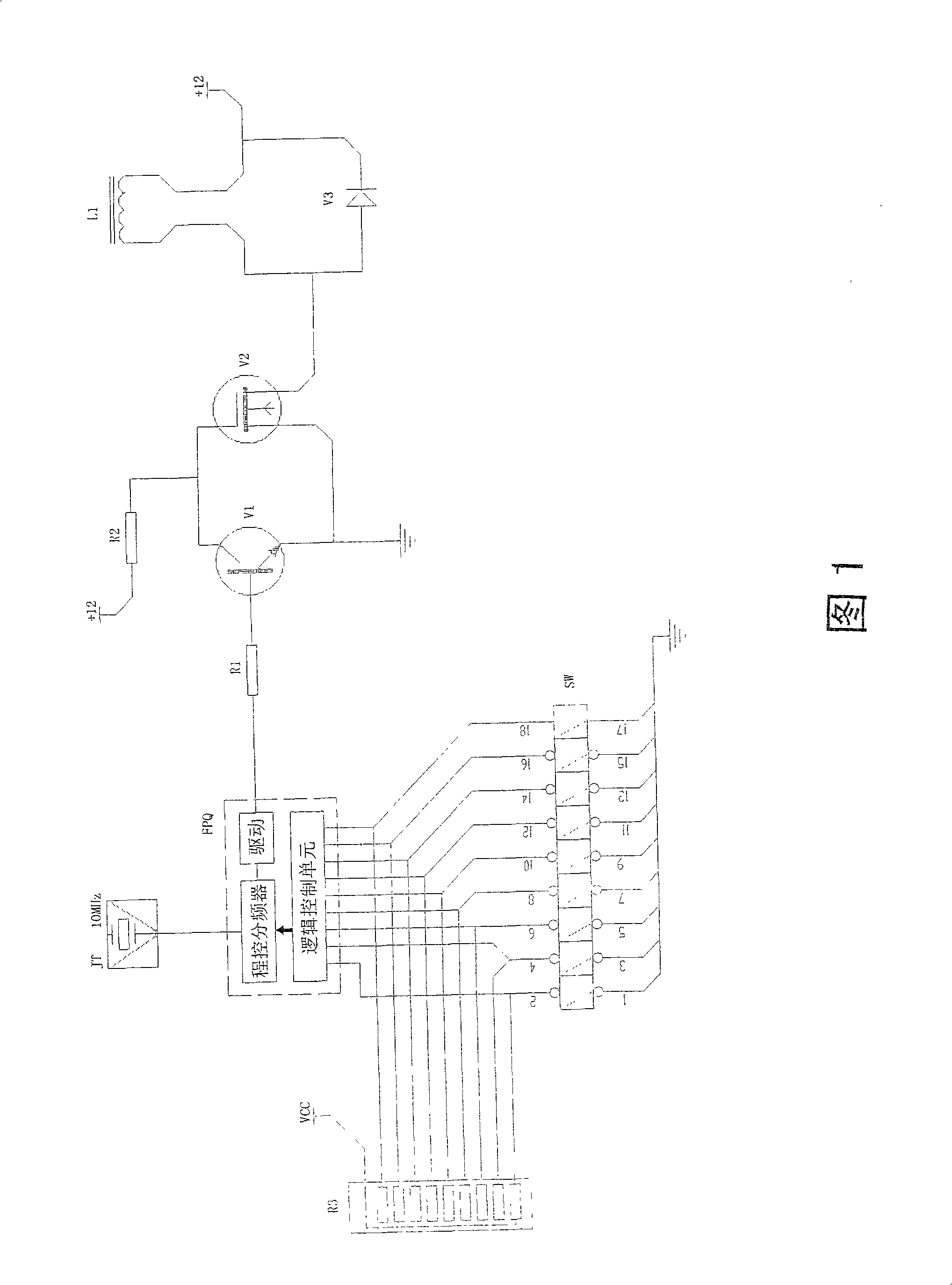
[0026] Fig. 1 is the schematic diagram of the electromagnetic pulse signal transmitting source circuit of the present invention, in which JT is a 10MHz crystal oscillator, and FPQ is a CPLD integrated circuit EPM7128STI. In this integrated circuit FPQ, there is an arbitrary frequency frequency divider logic module compiled by the special software MAXPLUS-II. The frequency divider depends on the external resistor R3 and the SW switch (the actual switch network is a rotary 9 to 1 band The frequency selection network composed of switch) divides the pulse frequency generated by the crystal oscillator JT into nine pulse frequencies of 500Hz to 1.3KHz representing the speed limit of 50km / h to 130km / h. Choose to output a certain frequency pulse signal at different positions. Resistors R1, R2 and transistors V1, V2 form an amplifying ...


PUM


Abstract

The invention provides an active speed limit controlling device of motor-vehicle-involved mode, aiming at solving passiveness and limitation which are introduced by the traditional 'electronic eye' speed detecting method and the novel method of 'interval speed detection' in the detection of an over-speed vehicle on a freeway. The active speed limit controlling device comprises an emission source of a speed-limited value signal, a vehicle-bone signal receiver, a Hall sensor, a speed limit indicator and a circuit thereof, an over-speed alarming circuit, a switch circuit of an electronically-controlled accelerating pedal and components thereof, a single-chip speed controlling software and so on. The emission source is arranged under or on the ground of the entrance of a freeway, with different pulse frequencies representing different vehicle speed limit values. When the vehicle exceeds the speed limit, the system device emits an over-speed alarming signal, and the driver needs to decelerate by self, otherwise, at the end of the alarm, the accelerating pedal does not take effect to the oil-supplied control instantly, and recovers after automatically decelerating the vehicle to a given value in a punishing way. The active speed limit controlling method and the process thereof are carried out repeatedly, which leads the vehicles to be driven in order, reduces the occurrence of traffic jam, and prevents a traffic accident which is easily caused by over-speed.

Description

Technical field: [0001] The invention relates to an intervening speed control device for overspeeding motor vehicles, more specifically, an active speed limit control device for speeding vehicles in violation of regulations in expressway traffic safety management. Background technique: [0002] At present, the speed management and control on the expressway is mainly for the traffic safety management department to set up an obvious speed limit sign in the form of a sign at the intersection of the expressway section where the speed limit is required, and to give warning speed limit prompts to vehicles entering the speed limit section. Several speed limits such as 120km / h, 110km / h, 100km / h, and 80km / h stipulated in my country's traffic regulations are mainly set according to the different grades of expressways or the environmental road conditions where they are located. This is basically the case in countries all over the world. On some complex and special road sections, large ...

Claims


Application Information

Patent Timeline
Patent Type & Authority Applications(China)
IPC IPC(8): G08G1/09
Inventor 孙世强李宗懋李扬荣
Owner 李扬荣
Why Eureka
Try Eureka