Non-hydraulic plate quenching device for steel belt continuous quenching and steel belt cooling method

A technology of a quenching device and a cooling method, applied in the direction of quenching device, furnace, heat treatment equipment, etc., can solve the problems such as the inability to improve the quenching efficiency of steel plates, the decrease of the thermal conductivity of the separated steel plates, and the slow cooling rate of the steel plates, etc. The effect of improving the finish and flatness, and improving the production efficiency

Inactive Publication Date: 2009-01-21
ZHEJIANG BAINAI STEEL STRIP
View PDF1 Cites 19 Cited by
  • Summary
  • Abstract
  • Description
  • Claims
  • Application Information

AI Technical Summary

Problems solved by technology

It has the following disadvantages: (1) the intermittent quenching method can only be quenched one by one (the specification of each steel plate in the embodiment is 1000mm×2000mm), and the production efficiency is low; (2) the cooling water circulation pipeline The contact area with the partition steel plate is small, which leads to the decrease of the thermal conductivity of the partition steel plate, slows down the cooling speed of the steel plate, and leads to the inability to improve the quenching efficiency of the steel plate

Method used


Image

  • Non-hydraulic plate quenching device for steel belt continuous quenching and steel belt cooling method
  • Non-hydraulic plate quenching device for steel belt continuous quenching and steel belt cooling method

Examples


Embodiment Construction

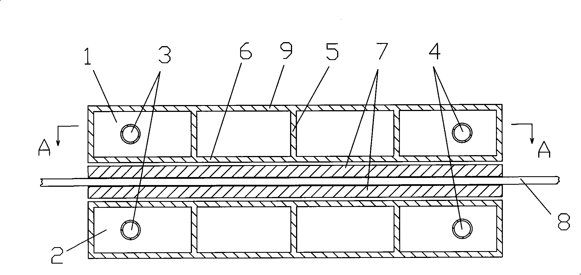
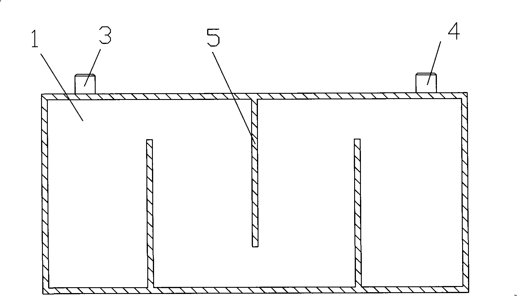
[0018] see figure 1 and figure 2 , the quenching device includes an upper water tank 1 and a lower water tank 2, and a continuously moving steel belt 8 passes between the two water tanks. The upper and lower water tanks 1 and 2 are respectively provided with a water inlet 4 and a water outlet 3. , 2 are respectively provided with three groups of water guide plates 5 for guiding the flow of water. Two water tanks are pressing plate 6 on one side close to the steel band, and the other side is loam cake 9, and water guide plate 5 is connected with pressing plate 6 and closely contacts, and is padded with protective plate 7 between pressing plate 6 and steel band 8.

[0019] The water deflectors 5 in the upper and lower water tanks 1 and 2 are usually arranged in three or five groups.

[0020] The protective plate 7 is made of materials with excellent thermal conductivity, small surface friction coefficient, high melting point, and deformability. Specifically, materials such as...


PUM


Abstract

The invention discloses a quenching device without a hydraulic plate with continuous quenching of a steel belt and a steel belt cooling method. The quenching device without the hydraulic plate comprises an upper water tank and a lower water tank, wherein a water inlet and a water outlet are arranged on each water tank; a plurality of water guide plates are arranged inside the water tanks; the steel belt passes through the two water tanks; one side of each water tank close to the steel belt is provided with a pressure plate; and a protective plate is arranged between the pressure plate and the steel belt. The quenching steel belt cooling method without the hydraulic plate transfers heat of the heated steel belt to flowing water by utilization of solid heat conduction and the temperature of the steel belt is quickly reduced to below the martensite transition temperature Ms without the necessity of direct cooling of liquid, thereby the steel belt texture is transformed from austenite to martensite. The quenching device without the hydraulic plate and the steel belt cooling method have the advantages of no necessity of any liquid quenching medium, no environmental pollution, simple equipment, high production efficiency, and good surface finish degree and flatness.

Description

technical field [0001] The invention relates to a continuous quenching technology for steel strips, in particular to a non-hydraulic plate quenching device for continuous quenching of steel strips and a cooling method for steel strips, which are suitable for continuous quenching steel strip production lines. Background technique [0002] Spring steel belt has high elasticity and wear resistance, and is widely used in automobile clutches, masonry tools, rolling door springs, iron sheets for shoes, needles for textiles and other products. The spring steel strip is generally made of medium-high carbon steel or alloy steel such as 50#, 65Mn, T8A, etc. It needs to go through the heat treatment process of quenching and tempering to obtain the combination of hardness and toughness, so that it has high elasticity and wear resistance. [0003] In production, the steel strip usually adopts continuous quenching and cooling equipment to rapidly cool the steel strip in the high-temperatu...

Claims


Application Information

Patent Timeline
Patent Type & Authority Applications(China)
IPC IPC(8): C21D9/56C21D1/62
Inventor 李益明
Owner ZHEJIANG BAINAI STEEL STRIP
Why Eureka
Try Eureka