Apparatus for improving absorption rate and emission rate in infrared heat wave nondestructive detection

A non-destructive testing, infrared thermal wave technology, applied in material defect testing and other directions, can solve problems such as damage, pollution, limit the application of infrared thermal wave non-destructive testing technology, etc., to improve the absorption rate and infrared emissivity, and improve the detection effect.

Inactive Publication Date: 2009-02-18
CAPITAL NORMAL UNIVERSITY +1
View PDF0 Cites 4 Cited by
  • Summary
  • Abstract
  • Description
  • Claims
  • Application Information

AI Technical Summary

Problems solved by technology

However, for some corrosion-prone or precise aerospace and aviation components, this anti-reflection treatment will cause a certain degree of pollution or even damage to the surface of the measured object, which limits the application of infrared thermal wave nondestructive testing technology in this area

Method used


Image

  • Apparatus for improving absorption rate and emission rate in infrared heat wave nondestructive detection
  • Apparatus for improving absorption rate and emission rate in infrared heat wave nondestructive detection
  • Apparatus for improving absorption rate and emission rate in infrared heat wave nondestructive detection

Examples


Embodiment 1

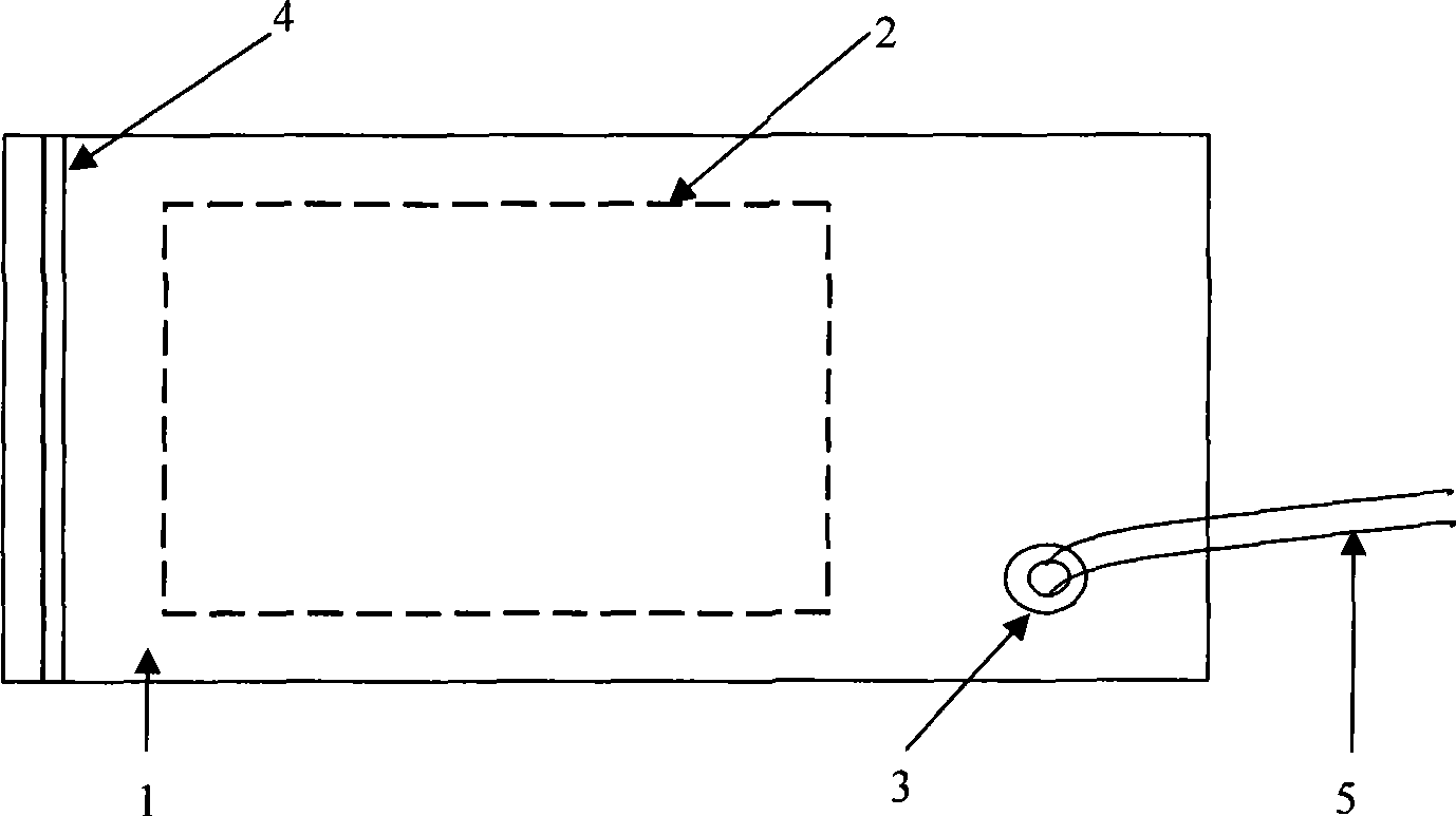
[0018] Example 1: For a vacuum coating device independent of the detection system, see figure 1 Firstly, the vacuum bag 1 of suitable material should be selected, and the material of the vacuum bag 1 is required to be a polymer film with high elasticity and high tensile strength, which has good visible light absorption rate and infrared emission rate. Put the detected object 2 into the vacuum bag 1 and seal the vacuum bag 1 with the buckle 4, pump out the air in the vacuum bag 1 through the air hole 3, so that there is no air gap between the film of the vacuum bag 1 and the detected object 2 In close contact, the air hole 3 is connected to the vacuum device through the air pipe 5 . To further increase the visible light absorption rate and infrared emission rate of the film surface, uniform spraying treatment can be carried out on the film surface.

Embodiment 2

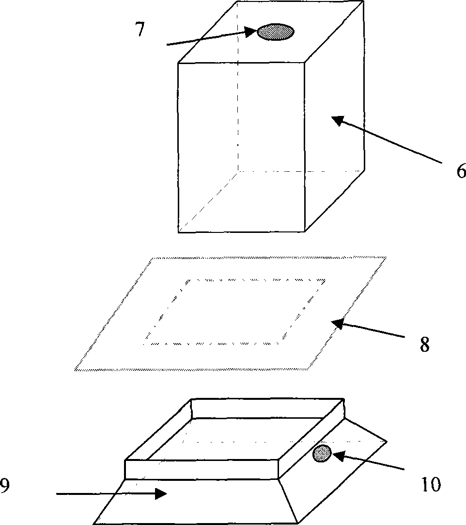
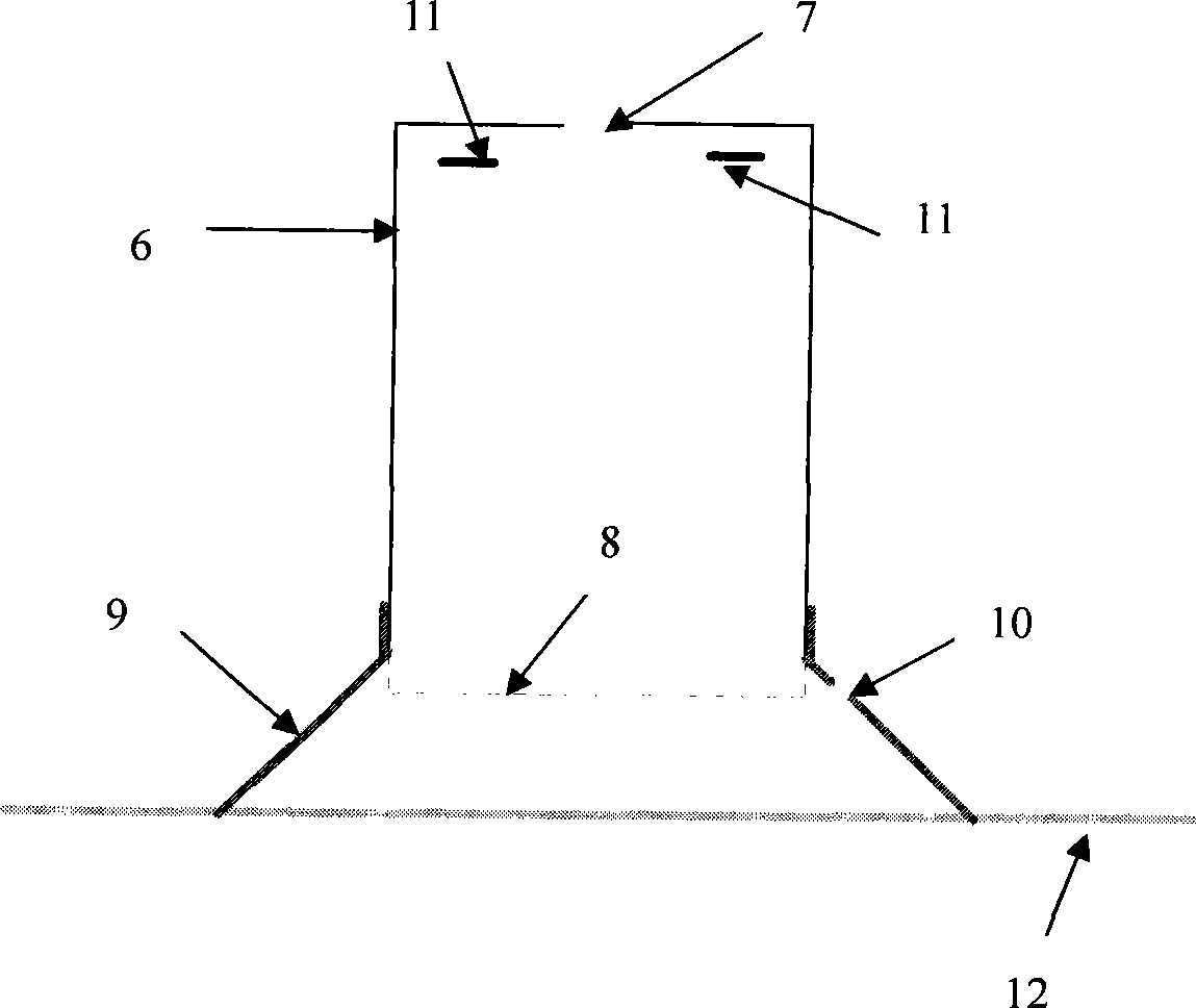
[0019] Example 2: The vacuum coating device in the infrared thermal wave non-destructive testing system see figure 2 and image 3 . Add a rubber skirt 9 between the flashlight cover 6 and the surface 12 of the object to be measured. The rubber material used to make the rubber skirt 9 should have certain elasticity. The shape and size of the upper port of the rubber skirt 9 are the same as those of the flashlight cover 6. The shape and size of the port match, and the shape and radian of the port under the rubber skirt 9 need to be designed according to the shape and surface radian of the test piece. Have air-breathing hole 10 on rubber skirt circumference 9. Cover the upper port of the rubber skirt 9 with the film 8, then insert the lower port of the flash cover 6 into the upper port of the rubber skirt 9, and at the same time clamp the film 8, during the measurement, the lower port of the rubber skirt 9 Place it on the surface 12 of the measured object, so that a closed sp...


PUM


Abstract

The invention relates to the infrared thermal wave nondestructive detection techniques, in particular to a device which can improve the surface absorption rate and emissivity of the tested object in the infrared thermal wave nondestructive detection process. The method adopted by the invention is to select a functional membrane with good visible light absorption rate and infrared emissivity in the infrared thermal wave nondestructive detection process to cover the tested object; and the air between the surface of the tested object and the membrane is pumped out to enable the functional membrane to be closely contacted with the tested object. The invention is characterized by improving a flashlight mask based on the existing infrared thermal wave nondestructive detection system so as to achieve the method. The invention causes no pollution and damage to the tested object in the detection process and can improve the visible light absorption rate and infrared emissivity of the tested object so as to greatly improve the infrared thermal wave nondestructive detection result on the object which has high surface reflectivity and can not be treated with spray painting; and the invention is suitable for the infrared thermal wave nondestructive detection of corrosive or precision aerospace and aviation devices.

Description

[0001] The patent application of the present invention is a divisional application of the invention patent application with the filing date of December 2, 2005, the application number of 200510125666.0, and the invention title of "Method and device for improving absorption rate and emissivity in infrared thermal wave non-destructive testing". technical field [0002] The invention relates to an infrared thermal wave nondestructive detection technology, in particular to a method and a device for increasing the surface absorptivity and emissivity of a measured object during the infrared thermal wave nondestructive detection process. Background technique [0003] Infrared thermal wave non-destructive testing technology is based on thermal wave theory, heats the surface of the object to be detected, uses infrared thermal imaging cameras and other equipment to record changes in the temperature field of the object's surface, and detects whether there are defects inside the object by...

Claims


Application Information

Patent Timeline
Patent Type & Authority Applications(China)
IPC IPC(8): G01N25/72
Inventor 王迅段玉霞金万平冯立春张存林
Owner CAPITAL NORMAL UNIVERSITY
Why Eureka
Try Eureka