Top burning hot blast stove using annular airflow spray upward with premixing combustion and reflux heating

A recirculation heating, premixed combustion technology, applied in combustion methods, brick blast furnaces, lighting and heating equipment, etc., can solve the problems of incomplete combustion, unstable combustion, poor load regulation performance, etc., to reduce exhaust gas temperature and emissions quantity, good economic and social benefits, and the effect of reducing environmental pollution

Active Publication Date: 2009-03-11
河南省豫兴热风炉工程技术有限公司
View PDF0 Cites 15 Cited by
  • Summary
  • Abstract
  • Description
  • Claims
  • Application Information

AI Technical Summary

Problems solved by technology

Throughout the existing hot blast stove combustion devices, there are problems of varying degrees in structure and combination, often appearing in the hot blast stove. Combination between the device and the vault), resulting in incomplete or unstable combustion, poor load regulation performance, etc.
If there are structural problems in the coordination between the combustion device and the heat transfer-regenerator bod

Method used


Image

  • Top burning hot blast stove using annular airflow spray upward with premixing combustion and reflux heating
  • Top burning hot blast stove using annular airflow spray upward with premixing combustion and reflux heating
  • Top burning hot blast stove using annular airflow spray upward with premixing combustion and reflux heating

Examples


Embodiment Construction

[0009] Specific embodiments of the present invention will be described in detail below in conjunction with the accompanying drawings.

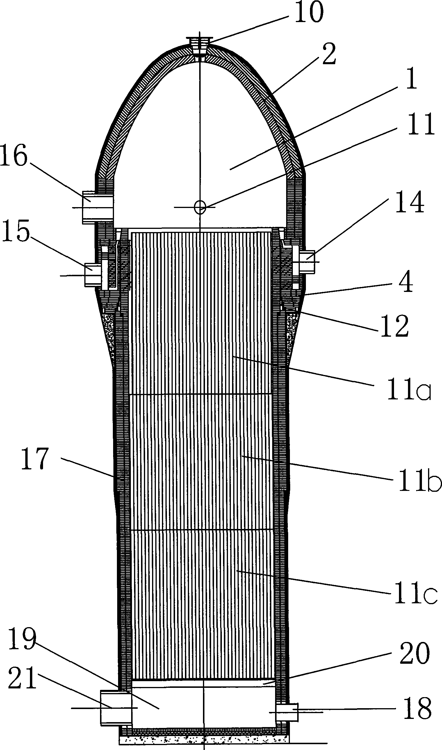
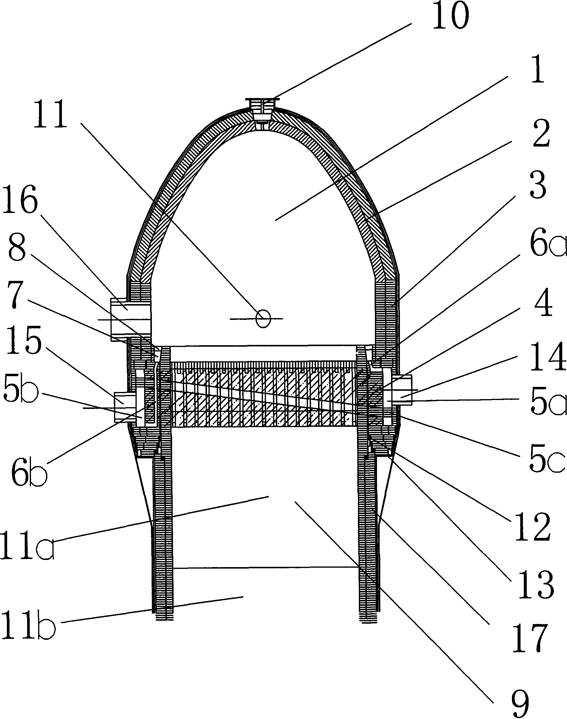
[0010] Depend on figure 1 , figure 2 As shown, the present invention includes a vault, a combustion chamber, a body of furnace and a burner, the vault is placed on the top of the burner, the burner is placed on the top of the body of furnace, the bottom of the body of furnace has a grate 20, and the bottom of the grate is a cold air chamber 19 , there are flue gas outlet pipe 21 and cold air inlet pipe 18 on the side wall of the cold air chamber, the combustion chamber 1 is formed between the straight part 3 on the upper part of the burner 4 and the vault 2, and the hot air outlet pipe communicating with the combustion chamber is arranged on the straight part 16. The burner is composed of an outer wall and an inner wall. There is a regenerator 9 at the lower part. The upper part of the furnace body forming the regenerator is coaxially insert...


PUM


Abstract

The invention relates to a top-firing hot blast furnace which adopts upper spraying, premixing, firing, reflux and heating by annular airflow and effectively solves the problems of the rationality and stability of the fluid flow in the hot blast furnace and the sufficiency and uniformity of the mixing of different fluids. The top-firing hot blast furnace has the following structure: a vault is positioned on a burner of the upper part of a furnace body; the lower part of a furnace grate under the furnace body is provided with a cold wind chamber; a flue gas outlet pipe and a cold wind inlet pipe are arranged on the sidewall of the cold wind chamber; a combustion chamber is formed between a straight cylinder part on the upper part of the burner and the vault; a hot blast outlet pipe is arranged on the straight cylinder part; the lower part of the burner is provided with a heat storage chamber; the outer wall of the burner is positioned on an outer supporting annular plate of the upper part of the furnace body; the inside of the burner is separated into a coal gas distribution circuit and an air distribution circuit by a partition wall of an oblique circuit; the outer ends of the coal gas distribution circuit and the air distribution circuit are provided with a coal gas inlet pipe and an air inlet pipe respectively; a conduit is formed between the upper parts of the outer wall and the inner wall of the burner; the coal gas distribution circuit and the air distribution circuit are connected with an annular airflow premixing conduit through the respective nozzle tube distributed on the peripheral wall of the burner; and a flow equalizing and obstructing baffle plate is formed between the upper part of the conduit and the combustion chamber. The top-firing hot blast furnace has good economical and social benefits.

Description

1. Technical field [0001] The invention relates to a top-combustion hot blast stove which adopts annular airflow upward spraying, premixed combustion and backflow heating for fuel combustion and flow heat transfer in the field of thermal energy engineering. 2. Background technology [0002] The hot blast stove is an indispensable and important auxiliary equipment in blast furnace ironmaking. It is a combination of a combustion device (consisting of a burner and a combustion chamber) and a heat transfer-regeneration device (consisting of a regenerator and checker bricks). The difference in the relative position of the two devices can be divided into internal combustion type (two devices are placed in parallel and in a cylindrical device), external combustion type (two devices are placed in parallel and each is placed in a cylindrical device) and top combustion type (the two devices are placed up and down, and the combustion device is on top) three large structural forms. As ...

Claims


Application Information

Patent Timeline
IPC IPC(8): C21B9/00
CPCC21B9/02F23L15/02C21B9/16C21B9/14Y02E20/34Y02P10/32
Inventor 刘世聚陈维汉刘力铭范剑超
Owner 河南省豫兴热风炉工程技术有限公司
Why Eureka
Try Eureka