Exhaust gas recirculation system

A technology of exhaust gas and recirculation, which is applied in exhaust gas recirculation, fuel heat treatment device, charging system, etc., can solve problems such as corrosion, improve EGR rate, maintain NOx reduction effect, and improve cooling efficiency.

Inactive Publication Date: 2009-03-18
KOMATSU LTD
View PDF1 Cites 5 Cited by
  • Summary
  • Abstract
  • Description
  • Claims
  • Application Information

AI Technical Summary

Problems solved by technology

[0010] However, in order to reduce the weight of the air-cooled aftercooler, the air-cooled aftercooler is usually made of a material such as aluminum, so there is a high possibility of corrosion due to the sulfur component contained in the EGR gas, and the air-cooled aftercooler cannot be used to cool the mixture. gas

Method used


Image

  • Exhaust gas recirculation system
  • Exhaust gas recirculation system
  • Exhaust gas recirculation system

Examples


no. 1 approach

[0039] 1. Overall structure

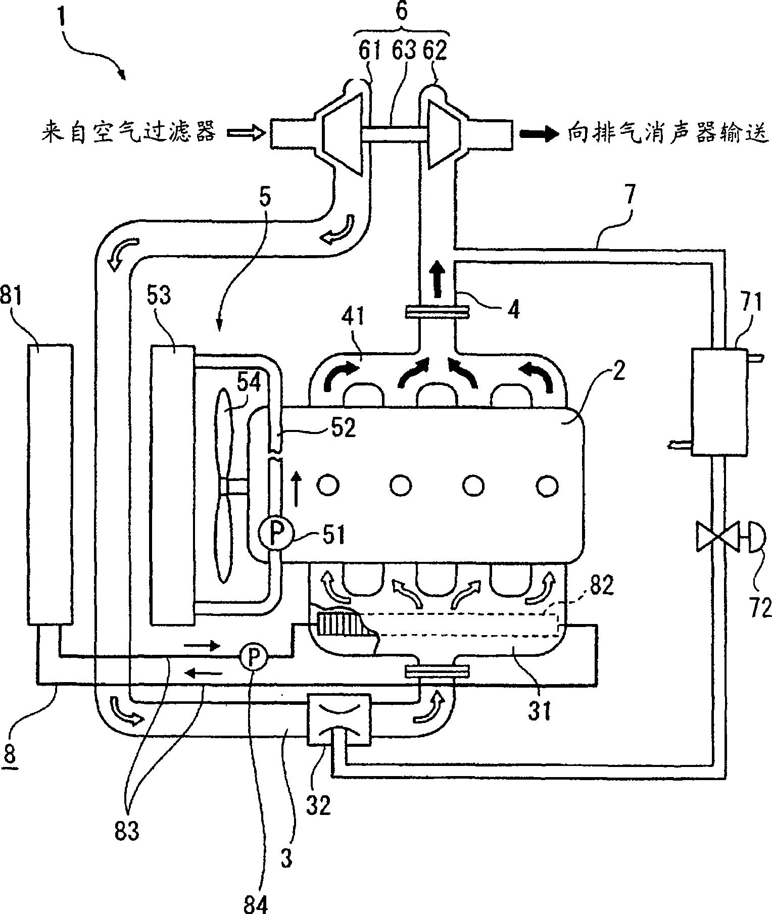
[0040] figure 1 It is a schematic diagram showing the EGR system of the diesel engine (internal combustion engine) 1 according to the first embodiment of the present invention.

[0041] The structure of the diesel engine 1 has: an inline four-cylinder engine body 2, an intake path 3 for supplying intake air to the combustion chamber, an exhaust path 4 for discharging exhaust gas to the outside of the combustion chamber, and an engine cooling refrigeration unit for cooling the diesel engine 1. The agent circulation path 5 is provided with an exhaust turbocharger 6 straddling between the upstream side of the intake path 3 and the downstream side of the exhaust path 4 . In addition, these devices are controlled by an engine controller that outputs a control signal through an operator's operation. figure 1 In , illustration of the engine controller is omitted.

[0042] Between the intake path 3 and the engine body 2, an intake manifold 31 is instal...

no. 2 approach

[0076] Next, a second embodiment of the present invention will be described. In addition, in the following description, the same code|symbol is attached|subjected to the same part as what already demonstrated, and the description is abbreviate|omitted.

[0077] In the aforementioned first embodiment, the liquid-cooled cooling device 8 employs a cooling water circulation structure independent of the engine-cooling refrigerant circulation path 5 of the diesel engine 1 .

[0078] In contrast, as Figure 4 As shown, the liquid-cooled cooling device 18 of the second embodiment is different in that a branch pipe path 182 is provided in a part of the piping path 52 for circulating the cooling water in the engine cooling refrigerant circulation path 5 of the diesel engine 1 , the cooling water is supplied to the heat exchanger 181 by the pump 51 .

[0079] In the present embodiment, since a part of the cooling water in the engine cooling refrigerant circulation path 5 is configured ...

no. 3 approach

[0088] Next, a third embodiment of the present invention will be described.

[0089] In the aforementioned first embodiment, one exhaust turbocharger 6 is installed in the diesel engine 1 .

[0090] In contrast, as Image 6 As shown, the third embodiment is different in that a twin-turbo type in which two exhaust turbochargers 6 are mounted on the diesel engine 1 is adopted.

[0091] In addition, the difference is that an air-cooled ATAAC (Air To Air After Cooler: air-to-air aftercooler) 33 is provided between the two exhaust turbochargers 6 on the side of the intake path 3 .

[0092] According to the third embodiment as described above, in addition to the basic effects described in the first embodiment, the two exhaust turbochargers 6 can also be used to improve the combustion rate, which is supplied to the intake manifold. The increase of the compression rate of the gas in 31 improves and promotes the cooling of the intake path 3. This cooling is performed by the ATAAC33 i...


PUM


Abstract

An exhaust gas recirculation system comprises an exhaust line (4) connected with an exhaust manifold (41) of an engine (1), an intake line (3) connected with an intake manifold (31) of the engine (1), and an EGR line (7) short-circuiting the exhaust line (4) and the intake line (3). The exhaust gas recirculation system supplies a portion of the exhaust gas discharged from the exhaust line (4) to the intake line (3) through the EGR line (7) and recirculates the exhaust gas to the engine (1). A liquid-cooling type cooling means (8) equipped with a heat exchanger (82) composed of a corrosion-resistant member is provided on the downstream side of the connecting position of the EGR line (7) in the intake line (3).

Description

technical field [0001] The present invention relates to an exhaust gas recirculation device, which has: an exhaust path connected to an exhaust manifold of an engine, an intake path connected to an intake manifold of the engine, the exhaust path and the The EGR path short-circuits the intake path, supplies a part of the exhaust gas discharged from the exhaust path to the intake path via the EGR path, and recirculates it in the engine. Background technique [0002] Conventionally, in order to reduce the combustion temperature of a diesel engine and suppress the generation of NOx, there is known an exhaust gas recirculation device that supplies a part of the exhaust gas discharged from the engine to the intake passage, that is, a so-called EGR (Exhaust-Gas Recirculation: Exhaust-Gas Recirculation: Exhaust-Gas Recirculation: gas recirculation) system. [0003] This EGR system connects the exhaust path connected to the exhaust manifold of the engine and the intake path connecte...

Claims


Application Information

Patent Timeline
Patent Type & Authority Applications(China)
IPC IPC(8): F02M25/07F02B29/04F02M31/20
CPCF02M25/0737F02M25/0714F02B29/0425Y02T10/121F02M25/0722F02M25/0707F02M25/0731F02M25/0711F02M26/05F02M26/08F02M26/11F02M26/19F02M26/28F02M26/32
Inventor 饭岛正木泽宏史
Owner KOMATSU LTD
Why Eureka
Try Eureka