Intelligent full-bridge soft-switching potentiostat

A potentiostat and soft switching technology, applied in the field of corrosion and protection, can solve the problems of lag in the application process of the potentiostat device, large power loss of switching devices, and no public reports, and achieve novel structural principles and avoid current impact. , the effect of small product volume and weight

Active Publication Date: 2009-04-01
SUNRUI MARINE ENVIRONMENT ENG
View PDF0 Cites 9 Cited by
  • Summary
  • Abstract
  • Description
  • Claims
  • Application Information

AI Technical Summary

Problems solved by technology

In the small and medium power range, the existing potentiostat equipment has disadvantages such as backward technical principles, large volume and weight, low efficiency, and high cost; a few manufacturers are launching switch-type potentiostat equipment or products designed and developed by themselves. Such products generally adopt traditional switching power supply topology and control methods, and the power loss of switching devices is relatively large.
Due to the rapid development of switching power supply control theory, technology and power devices in recent years, some electronic device manufacturers have introduced a new generation of power switching devices and highly integrated control chips. These devices are more suitable for the realization of some ideal control theories and methods. , which improves the overall performance of the switching power supply; these technologies and devices have been or are gradually being promoted in the field of switching power supplies, but the extensive application process of the above-mentioned technologies and devices for the potentiostat device is lagging behind, and the device with obvious application effect or successful application has not yet see public reports
In particular, there are no commercially available potentiostat devices that use such control devices and power devices to realize the soft switching process of power devices, reduce switching losses, and achieve predetermined control accuracy and effects.

Method used


Image

  • Intelligent full-bridge soft-switching potentiostat
  • Intelligent full-bridge soft-switching potentiostat

Examples


Embodiment

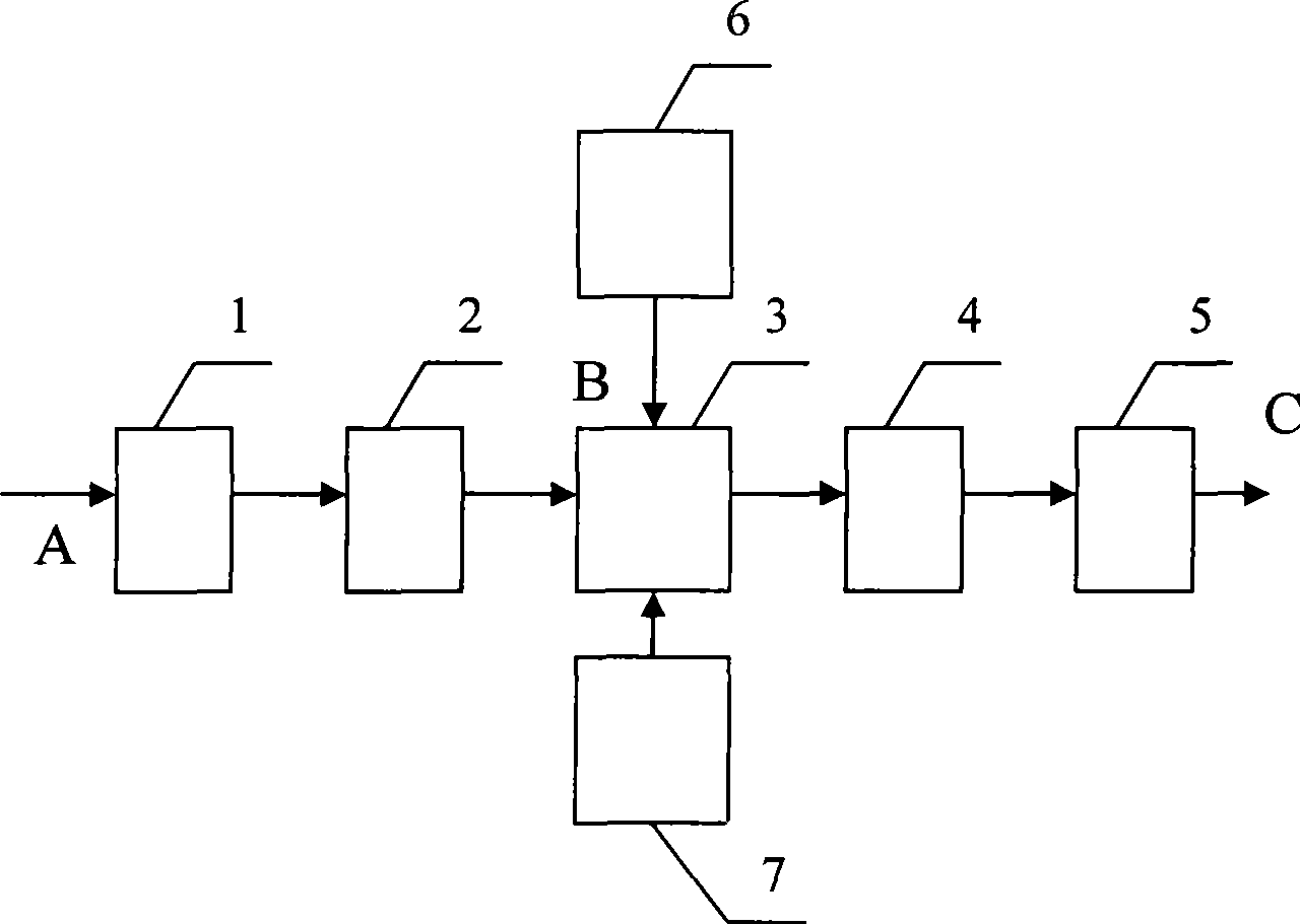
[0015] The main circuit of this embodiment is electrically connected by AC power rectification and filter circuits 1 and 2, full-bridge converter 3, soft switching circuit 7, high-frequency transformer 4, high-frequency output rectification and filter circuit 5, and pulse phase-shift control drive circuit 6. Combination structure; the input end of the AC rectification circuit 1 is connected to the AC input power supply, the output end is connected to the AC filter circuit 2, the output end of the AC filter circuit 2, the soft switching circuit 7, the pulse phase shift control drive circuit 6 and the input of the high frequency transformer 4 The ports are electrically connected to the full-bridge converter 3 in principle, the output end of the high-frequency transformer 4 is electrically connected to the input end of the high-frequency output rectification filter circuit 5, and the output end of the high-frequency output rectification filter circuit 5 outputs a DC power supply; t...


PUM


Abstract

The invention relates to an intellectual full bridge soft switching potentiostat, pertaining to the technical field of corrosion and protection. The input end of an AC rectification circuit is connected with an AC input power and the output end thereof is communicated with an AC filter circuit; the output end of the AC filter circuit, a soft switching circuit, a pulse phase shifting control drive circuit and the input port of a high frequency transformer are respectively electrically communicated with a full bridge converter schematically; the output end of the high frequency transformer is in butt-joint with the input end of a high frequency rectification filter circuit, and the output end of the high frequency rectification filter circuit outputs DC power; the pulse phase shifting control drive circuit is composed of a reference electrode separation amplification circuit, a phase shift controller, a switch valve drive circuit, a signal comparison control circuit, a liquid-crystal display and a keying circuit as well as a monolithic system which are communicated electrically. The whole machine is characterized by novel structure and principle, simple principle, small product volume and light weight, low preparation cost and convenient application and operation and energy saving.

Description

Technical field: [0001] The invention belongs to the technical field of corrosion and protection, and relates to an applied current cathodic protection device, in particular to an intelligent full-bridge soft switch potentiostat. Background technique: [0002] At present, the potentiostat equipment used in impressed current cathodic protection systems such as ships, port facilities, ocean engineering and buried pipelines is generally based on thyristor and magnetic saturation variable current power supply. In the small and medium power range, the existing potentiostat equipment has disadvantages such as backward technical principles, large volume and weight, low efficiency, and high cost; a few manufacturers are launching switch-type potentiostat equipment or products designed and developed by themselves. Such products generally adopt traditional switching power supply topology and control methods, and the power loss of switching devices is relatively large. Due to the rapi...

Claims


Application Information

Patent Timeline
Patent Type & Authority Applications(China)
IPC IPC(8): C23F13/22
Inventor 王文茂王智磊刘雪雷
Owner SUNRUI MARINE ENVIRONMENT ENG
Why Eureka
Try Eureka