Stove combustor and process for manufacturing combustion disk in combustor

A technology of burners and combustion discs, applied in the direction of burners, gas fuel burners, combustion methods, etc., can solve the problems of gas pressure damage, gas lack of flow, slow fire transmission, etc. Full, fully burning effect

Inactive Publication Date: 2009-04-01
ZHEJIANG SHUAIKANG ELECTRIC
View PDF0 Cites 21 Cited by
  • Summary
  • Abstract
  • Description
  • Claims
  • Application Information

AI Technical Summary

Problems solved by technology

The walls of the air cavity of the combustion disc 2 and the fire cover 3 of the traditional technology are relatively thick, and the space in the air cavity is occupied when the screw is fastened, and the inner diameter cross-sectional area of ​​the air cavity is reduced, causing the gas to go through multiple turns, and the gas pressure is damaged again , especially artificial gas with a fast burning speed is easy to temper, (tempering is a major defect of the burner)
In order to ensure a sufficient diameter of the air cavity, if the size is increased outward, the secondary air passage at the bottom of the combustion pan will inevitably be reduced. Insufficient supplementary secondary air will also cause excessive carbon monoxide in the flue gas
At the same time, it is not conducive to the heat balance of the burner, and

Method used


Image

  • Stove combustor and process for manufacturing combustion disk in combustor
  • Stove combustor and process for manufacturing combustion disk in combustor
  • Stove combustor and process for manufacturing combustion disk in combustor

Examples


Embodiment Construction

[0050] Below in conjunction with accompanying drawing, the present invention is described in further detail:

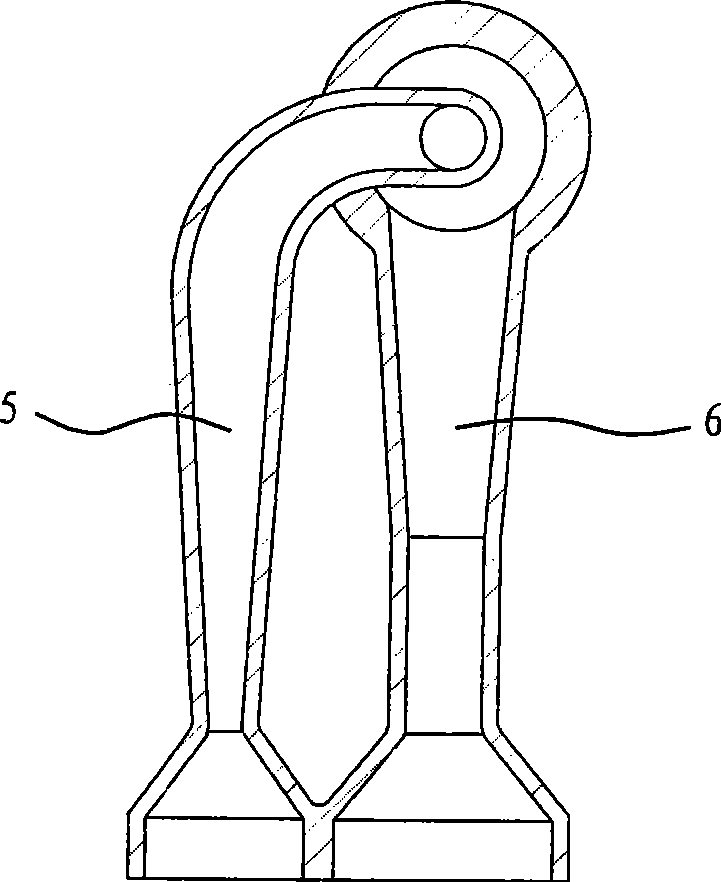
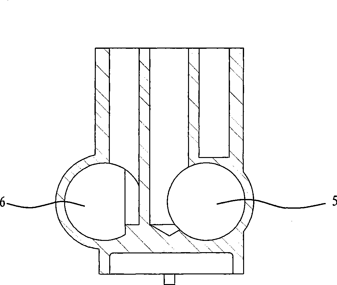
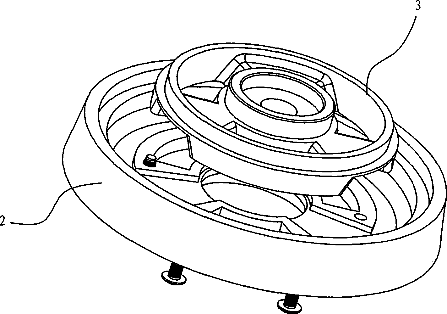
[0051] Such as Figure 5 to Figure 12 As shown, a cooker burner provided by the present invention includes a base 1, a gas injection pipe connected to the base 1, a combustion disc 2, a flame distributor communicated with the combustion disc 2, and an ignition device. In the present invention, the ignition device is an ignition needle 8 . The base 1 comprises a central fire gas pipe 11 and a main fire gas pipe 12, the central fire gas pipe 11 is set in the main fire gas pipe 12, and the combustion disc 2 communicates with the central fire gas pipe 11 and the main fire gas pipe 12 respectively; The central firearm 3 and the outer firearm 4, the central firearm 3 and the outer firearm 4 communicate with the combustion disk 2 respectively, and the gas injection pipe includes a central fire gas injection pipe 5 and a main fire gas injection pipe 6, and the central fire g...


PUM


Abstract

The invention relates to a burner of cooking utensils and a preparation technology of a tray for combustion in the burner. The burner comprises a distributor, a tray for combustion, a base seat and an ignition device, wherein, the distributor consists of an external distributor and an internal distributor; the tray for combustion is provided with three rings of fire, three grooves for flame stabilization and four overall channels, has a maximum sectional drift diameter necessary for gas to enter into the tray for combustion and leaves four fan-shaped secondary air inlets at the bottom of the tray so as to ensure the secondary air supply to inner ring fire and central fire. Induction tunnels communicated with a gas pipe for main fire and a gas pipe for central fire are arranged on two staggered horizontal planes with independent gas intake, which greatly saves gas kinetic energy and reduces resistance in air intake by the induction tunnels. The burner can ensure enough primary air intake without yellow flame, flashback and blow-off for more full burning. The preparation technology provided by the invention can ensure high surface smoothness of the tray for combustion and high precision in dimension of an inner cavity, smooth flow of gas and reduction in loss of gas kinetic energy so as to improve the efficiency of gas combustion.

Description

technical field [0001] The invention relates to a device used on a gas stove, in particular to a stove burner. The invention also relates to the preparation process of the combustion disk in the burner. Background technique [0002] At present, most of the burners in the gas stoves sold on the market and used at home have adopted three-ring fire and double-jet gas technology. The gas is ejected by two gas ejectors respectively, and the gas ejected by the two gas ejectors is divided into a central fire, an inner ring fire and an outer ring fire by a combustion disc and a flame distributor, forming a three-ring flame. Although the flame distribution of this type of burner is uniform, the area acting on the bottom of the pot is enlarged, and the combustion efficiency is improved. But there are also the following disadvantages: [0003] 1. If figure 1 , figure 2 As shown in FIG. 2 , there are two structural schematic diagrams of the connection between the existing double e...

Claims


Application Information

Patent Timeline
IPC IPC(8): F23D14/20F23D14/56F23D14/58F23D14/84B22C9/04
Inventor 邹国营俞根云
Owner ZHEJIANG SHUAIKANG ELECTRIC
Why Eureka
Try Eureka