
Diamond grinding wheel and method for manufacturing tool bit thereof

A technology of diamond grinding wheel and manufacturing method, which is applied in the direction of manufacturing tools, metal processing equipment, abrasives, etc., to achieve the effects of improving self-sharpening ability, expanding chip space, and improving performance

Active Publication Date: 2009-04-22
NANJING SANCHAO ADVANCED MATERIALS
View PDF0 Cites 23 Cited by
  • Summary
  • Abstract
  • Description
  • Claims
  • Application Information

AI Technical Summary

Problems solved by technology

However, the surface roughness Ra of silicon wafers processed by the original diamond precision polishing wheel is generally 0.05.

Method used


Image

  • Diamond grinding wheel and method for manufacturing tool bit thereof
  • Diamond grinding wheel and method for manufacturing tool bit thereof
  • Diamond grinding wheel and method for manufacturing tool bit thereof

Examples


Embodiment 1

[0020] Manufacturing method of diamond grinding wheel

[0021] (1) Preparation of mixture: the following components are made into powder by volume percentage: volume percentage is 25% phenolic resin, 25% diamond, 15% Fe 2 o 3 , 15% CeO 2 , 10% AL 2 o 3 , 10% Cu powder. The particle size of the diamond is 8000# (the diameter is between 0.1-0.3 microns). The particle size of the Cu powder is 400# (the diameter is between 40-50 microns).

[0022] Then, a pore-forming agent with 20% of the mass of the powder is added to the powder. The mass percent of the pore-forming agent consists of: 70% NaHCO 3 , and the rest are (NH 4 ) 2 CO 3 .

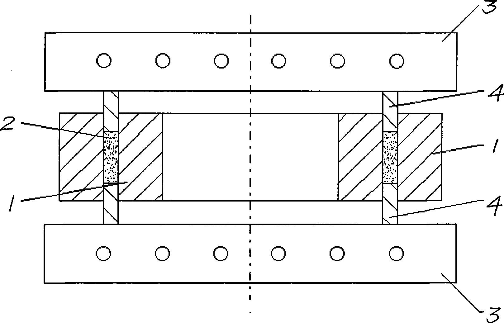
[0023] (2) see figure 2 , put the mixture into the cavity reserved in mold 1.

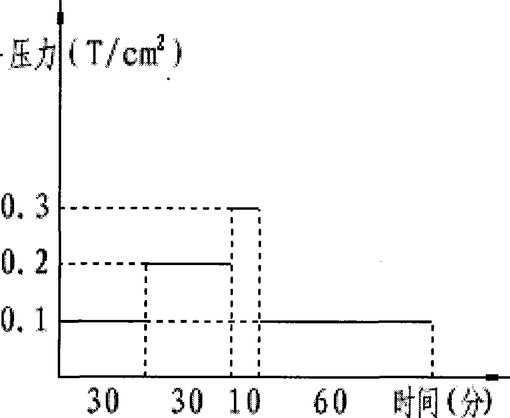
[0024] (3) The compound is heated and pressurized by the pressure ring 4 fixed on the heating plate 3, so that the compound 2 (see figure 2 ) is pressed to the required size; when the mixture is heated and pressurized, the pressure changes from 0.1t / CM wi...

Embodiment 2-5

[0028] The amount of the pore-forming agent added in Example 1 was changed to 30%, 40%, and 50% of the powder mass respectively, and the others were the same as in Example 1 to obtain Examples 2-5.

Embodiment 6-10

[0030] Change the volume percentage of the following components in the powder in Example 1 to: 30% phenolic resin, 20% diamond, and the others are the same as in Example 1 to obtain Example 6.

[0031] In the powder in embodiment 1, following component volume percent is changed to: 40% phenolic resin, 15% diamond, 10% Fe 2 o 3 . Others are the same as Example 1 to obtain Example 7.

[0032] In the powder material in embodiment 1, following component volume percentage is changed to: 35% phenolic resin, 25% diamond, 10% Fe 2 o 3 , 10% CeO 2 . Others are the same as Example 1 to obtain Example 8.

[0033] In the powder in embodiment 1, following component volume percentage is changed to: 40% phenolic resin, 25% diamond, 10% Fe 2 o 3 , 15% CeO 2 , 5% AL 2 o 3 , 5% Cu powder. Others are the same as Example 1 to obtain Example 9.

[0034] In the powder material in embodiment 1, following component volume percentage is changed to: 30% phenolic resin, 25% diamond, 15% Fe 2...


PUM

PropertyMeasurementUnit
Granularityaaaaaaaaaa
Diameteraaaaaaaaaa

Abstract

The invention provides a diamond grinding wheel for precise polishing for the surface of a silicon material and a manufacturing method for a tool bit thereof. Surface roughness Ra of a silicon chip polished by the grinding wheel is lower than 0.03, Ry is lower than 0.27, and Rz is lower than 0.29. The diamond grinding wheel comprises a steel basal body and the tool bit embedded in the steel basal body; the tool bit is manufactured by the following steps: putting a mixed material into a die cavity of a die; and heating and pressurizing the mixed material, so as to press the mixed material to the required size; and a preparation method for the mixed material comprises the following steps: preparing powder from the following components in volume percentage: 20 to 40 percent of phenolic resin, 12. 5 to 25 percent of diamond, 10 to 15 percent of Fe2O3, 10 to 15 percent of CeO2, 5 to 10 percent of Al2O3, and 5 to 10 percent of Cu powder; and then 20 to 50 percent powder mass of pore forming agent is added into the powder.

Description

technical field [0001] The invention relates to a manufacturing method of a diamond grinding wheel and a cutter head thereof, in particular to a resin-bonded diamond grinding wheel and a manufacturing method of a cutting head thereof for precise polishing of the surface of a silicon material. Background technique [0002] With the rapid development of the semiconductor industry, the use of chips is becoming more and more extensive, and the quality requirements of silicon wafer processing are constantly diversifying. In order to reduce processing costs, the polishing process of many silicon wafers specially used Instead of using the traditional method of grinding with loose grain abrasives, it is directly polished on a thinning machine with a fixed diamond precision polishing wheel. This polishing method can improve the polishing efficiency by nearly ten times, can better ensure the dimensions of the silicon wafers, and improve the polishing yield (the yield of the grinding a...

Claims


Application Information

Patent Timeline
IPC IPC(8): B24D18/00B24D3/32
Inventor 邹余耀
Owner NANJING SANCHAO ADVANCED MATERIALS
Learn More