Postweld heat welding method

A technology of thermal welding and welding, which is applied in the direction of welding accessories, heat treatment furnaces, heat treatment equipment, etc. It can solve the problems of affecting the metallurgical quality of the weld, low stress, and increasing the process, so as to save heating equipment, prevent stress corrosion cracking, Effect of improving fatigue life

Inactive Publication Date: 2009-04-22
王者昌
View PDF0 Cites 3 Cited by
  • Summary
  • Abstract
  • Description
  • Claims
  • Application Information

AI Technical Summary

Problems solved by technology

In this method, the water spraying position is only 20-30mm away from the center of the heat source (arc). Even if a special device is used, water vapor may enter the molten pool and arc area in case of a little carelessness, affecting the metallurgical quality of the weld.
This method can only achieve low stress, not stress-free welding
Low-alloy steel is prone to cold cracks (delayed cracks) during welding, which is often prevented by heat after welding, which not only increases the process, is labor-intensive, time-consuming and energy-consuming, but also requires special heating equipment

Method used


Image

  • Postweld heat welding method
  • Postweld heat welding method

Examples


Embodiment 1

[0013] Example 1 Low-carbon steel plate is welded without stress after welding (the "mechanical melting point" of low-carbon steel is 600°C)

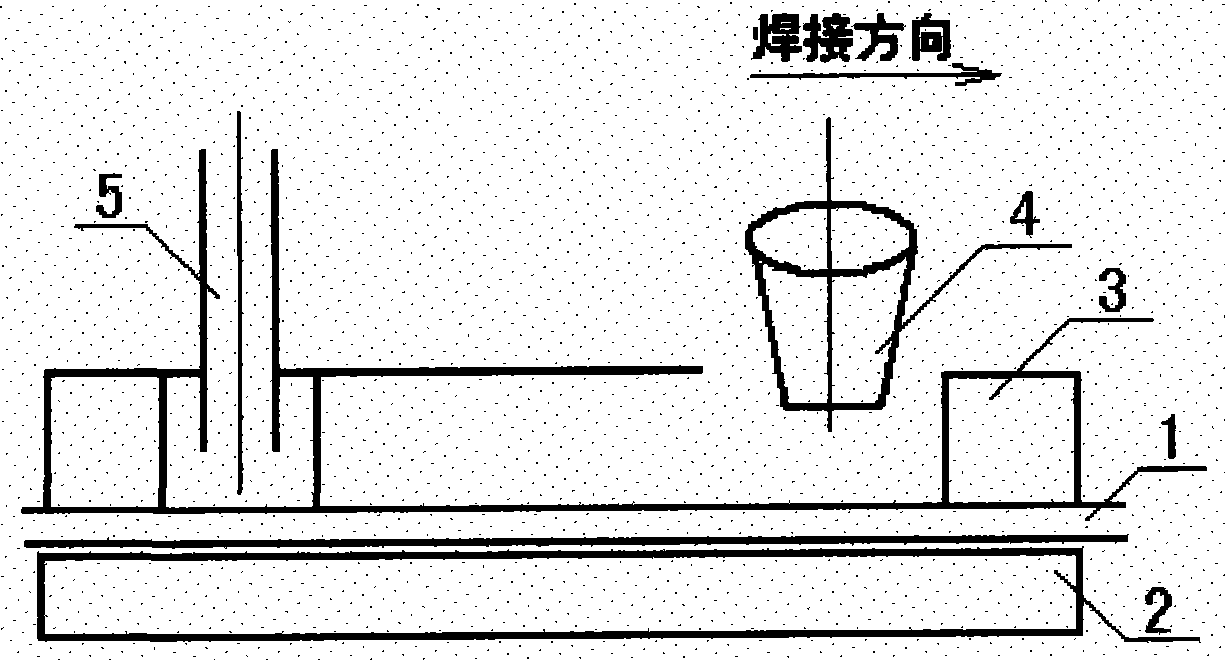
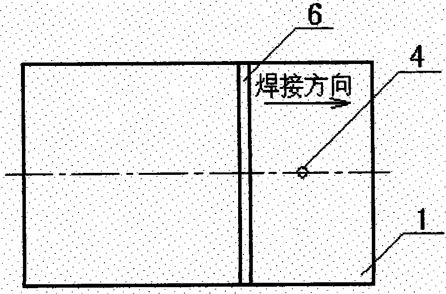
[0014] At 60 mm behind the welding heat source, the entire cross-section of the welded steel plate is subjected to post-welding heat with an oxygen-acetylene flame at a temperature of 610 ° C, and then naturally cooled.

[0015] There is no welding residual stress in the welding seam and near seam area of ​​low carbon steel plate.

Embodiment 2

[0016] Example 2 LF6 aluminum alloy plate is welded without stress after welding (the "mechanical melting point" of LF6 aluminum alloy is 420°C)

[0017] At 70 mm behind the welding heat source, the entire cross-section of the welded aluminum alloy plate is subjected to post-welding heat with an oxygen-acetylene flame at a temperature of 440 ° C, followed by natural cooling.

[0018] There is no welding residual stress in the welding seam and near seam area of ​​LF6 aluminum alloy plate.

Embodiment 3

[0019] Example 3 TC4 titanium alloy plate is welded without stress after welding (the "mechanical melting point" of TC4 titanium alloy is 800°C)

[0020] At 65 mm behind the welding heat source, the entire cross-section of the welded titanium alloy plate is subjected to post-welding heat with a linear laser beam at a temperature of 800 ° C, protected with argon gas, and then cooled naturally.

[0021] There is no welding residual stress in the weld seam and near seam area of ​​TC4 titanium alloy plate.


PUM


Abstract

The invention provides a welding-following postheat welding method, which is characterized in that along with welding, the cross section of a weldment is heated within a distance between 55 and 500 millimeters behind a welding heat source; the temperature is between 250 and 850 DEG C; and the cross section of the weldment is naturally cooled soon. The welding-following postheat welding method provided by the invention has the advantages that as a post heat source is far (more than 50 millimeters) from the welding heat source and has no aqueous medium, the method can not interfere with electric arc or affect the metallurgical quality of welding seams; the implementation of unstressed or low-stress welding can avoid or reduce the harm of the residual tensile stress of welding, and gets rid of a working procedure of eliminating stress after welding, thereby saving labor, time and energy; appropriate compressive stress existing in the welding seams and zones near the seams is favorable for preventing stress corrosion cracking and improving fatigue life; and welding-following postheat at a low temperature (250 to 350 DEG C) can prevent welding cold cracks and can leave out the working procedure of postheating after welding, which saves labor, time and energy and can leave out special heating equipment.

Description

technical field [0001] The present invention relates to welding methods. Background technique [0002] The weld seam and the near seam area are the weakest links of the welded structure, one of the important reasons is that there is a large residual tensile stress in the weld seam and the near seam area. The existence of residual tensile stress may cause adverse consequences such as welding cracks, structural brittle fracture, stress corrosion cracking and fatigue life reduction. Important structures often require post-welding stress relief treatment, which is labor-intensive, time-consuming, and consumes a lot of energy. Stress relief by heat treatment may also cause problems such as stress relief embrittlement and reheat cracks. Moreover, the elimination of stress is generally not completely thorough. For example, the vibration method can only eliminate about 50% of the residual stress. The heat treatment method is generally considered to be the most effective method of s...

Claims


Application Information

Patent Timeline
IPC IPC(8): C21D9/50B23K9/32
Inventor 王者昌
Owner 王者昌
Why Eureka
Try Eureka