Air power engine assembly

An engine assembly and aerodynamic technology, which is applied in the direction of unidirectional flow engines, variable displacement engines, machines/engines, etc., can solve problems such as failure to achieve energy saving, insufficient use of compressed air, energy waste, etc., and achieve improvement The effect of service life, small working resistance, stability and reliability

Inactive Publication Date: 2009-04-22
周登荣 +1
View PDF1 Cites 182 Cited by
  • Summary
  • Abstract
  • Description
  • Claims
  • Application Information

AI Technical Summary

Problems solved by technology

[0003] In the process of searching for new energy sources, it has been found that the thrust generated when compressed air is released can be used as a power source, and then its thrust can be converted into mechanical energy or electrical energy. Some devices that use compressed air to obtain power have been disclosed. For example, the patent No. 00122383.1 discloses a "gas-electric hybrid engine". This document uses electric energy and the thrust generated by compressed air to obtain energy. The generator used by this engine still needs to be driven by external energy, which indirectly uses external energy. , so the purpose of saving energy cannot be achieved. In addition, the compressed air in the engine is directly discharged after doing work, and the compressed air after discharge is not fully utilized, resulting in waste of energy.

Method used


Image

  • Air power engine assembly
  • Air power engine assembly

Examples


Embodiment Construction

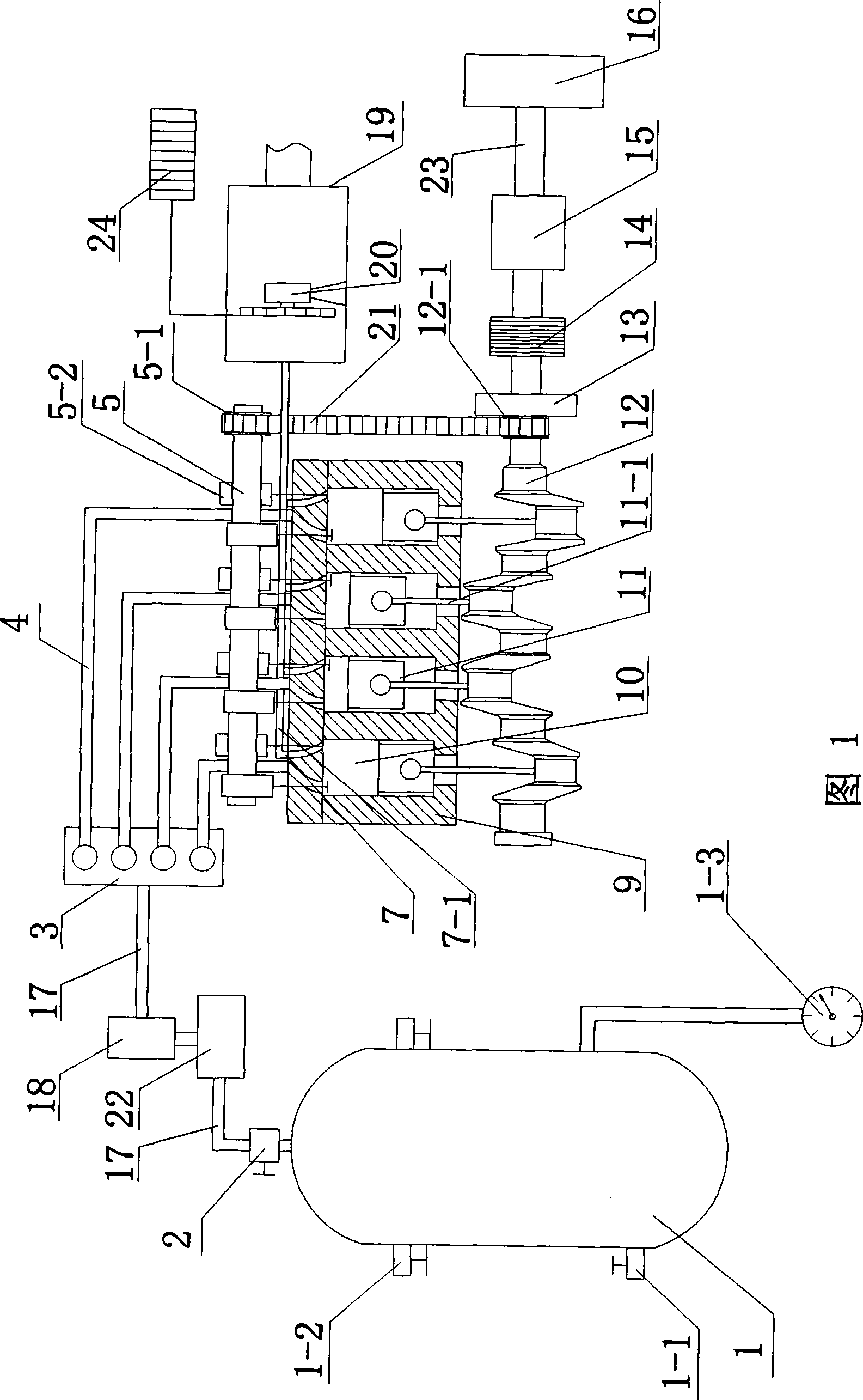
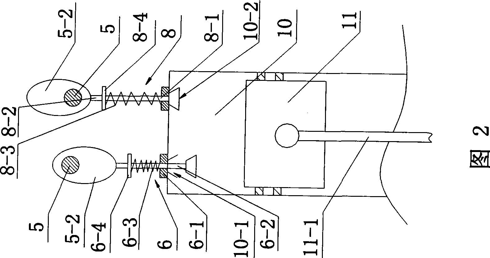
[0021] In order to further understand the invention content, characteristics and effects of the present invention, the following examples are given, and detailed descriptions are as follows in conjunction with the accompanying drawings:

[0022] Please refer to Figure 1, the aerodynamic engine assembly, including an air storage tank 1 connected to external compressed air, an air valve 2, an air distributor 3, an intake pipe 4, a camshaft 5, an air intake control device 6, and an exhaust pipe 7 , an exhaust control device 8, a cylinder 10 installed on the cylinder bed 9, a piston 11, a crankshaft 12, a linkage 13, a clutch 14, an automatic transmission 15 and a differential 16 connected to the outside. The gas storage tank 1 is equipped with an air intake valve 1-1 connected with external compressed air, and the air storage tank 1 is supplied with compressed air by adjusting the opening and closing of the air intake valve 1-1. The air storage tank 1 is equipped with a safety va...


PUM


Abstract

The invention relates to an air-powered engine assembly, which comprises an air tank, an air valve, an air distributor, an intake pipe, camshafts, an intake duct, an exhaust control device, air cylinders, pistons, crankshafts, couplers, clutches, automatic gearboxes and differentials connected with the outside. The assembly is characterized in that the air valve, a constant pressure chamber and a pressure controller are arranged between the air tank and the air distributor; the air distributor is connected with a plurality of air cylinders on an air cylinder gasket; each air cylinder is connected with an exhaust chamber through an exhaust manifold; the exhaust chamber is provided with a turbine generator which is connected with a storage batter; the air cylinders are provided with the camshafts for controlling the air intake and exhaust of the air cylinders; the air cylinders are provided inside with the pistons for driving the crankshafts to rotate; the camshafts and the crankshafts are connected by chains; and the crankshafts are connected with the differentials through the couplers, the clutches and the gearboxes in turn. Therefore, doing work through air compression rather than fuel, the air-powered engine assembly has the advantages of avoiding waste gas discharge and air pollution, along with reliable operation, convenient operation, economical efficiency, practicality and so on. In addition, due to recycle of the waste gas for power generation, the air-powered engine assembly saves energy and reduces costs.

Description

technical field [0001] The invention belongs to the field of engine manufacturing, in particular to an aerodynamic engine assembly using compressed air as a power source. Background technique [0002] Engines are widely used in various industries, and generally piston internal combustion engines are mainly used, and these engines use fuel oil as a power source. On the one hand, the engine using fuel oil as the power source pollutes the environment due to insufficient fuel combustion, which makes the exhaust gas contain a large amount of harmful substances, and on the other hand, the fuel used is extracted from petroleum. As we all know, oil is a non-renewable energy source on the earth. Therefore, with the massive exploitation and use of people, oil reserves are getting less and less. Therefore, it is necessary to develop new, clean, and pollution-free energy sources, especially new energy sources that are inexhaustible. [0003] In the process of searching for new energy s...

Claims


Application Information

Patent Timeline
Patent Type & Authority Applications(China)
IPC IPC(8): F01B17/02F03G7/00
CPCF01B17/02F01B17/025
Inventor 周登荣朱仕亮
Owner 周登荣
Why Eureka
Try Eureka