
Control method for stabilizing and enhancing sintered ring cooling wind temperature while smelting steel

A technology for iron and steel smelting and control devices, which is applied in furnace control devices, auxiliary non-electric temperature control, and electric temperature control, etc., and can solve the problems of reduced exhaust gas flow, instability, and impact on the steam output of waste heat boilers.

Inactive Publication Date: 2009-05-06
昆明阳光基业股份有限公司
View PDF0 Cites 25 Cited by
  • Summary
  • Abstract
  • Description
  • Claims
  • Application Information

AI Technical Summary

Problems solved by technology

In the actual working process of sinter cooling, due to the influence of various factors such as sinter flow rate, material layer thickness, air volume at the bottom of the trolley, lateral distribution uniformity of material layer thickness, sinter particle size, etc., the material The exhaust gas temperature on the upper part of the floor tends to fluctuate frequently. At the same time, due to the existence of cold air leakage from the lower part of the cooling trolley and hot air leakage from the upper part of the cooling trolley, the exhaust gas flow rate is relatively reduced and unstable. The combination of the above factors is serious It affects the steam output of the waste heat boiler, which in turn seriously affects the stability of the power generation system

Method used


Image

  • Control method for stabilizing and enhancing sintered ring cooling wind temperature while smelting steel
  • Control method for stabilizing and enhancing sintered ring cooling wind temperature while smelting steel
  • Control method for stabilizing and enhancing sintered ring cooling wind temperature while smelting steel

Examples


Embodiment Construction

[0032] The present invention will be further described below by way of examples, but not limited to examples.

[0033] Take Yunnan Yuxi Xinxing Iron and Steel Co., Ltd. as an example.

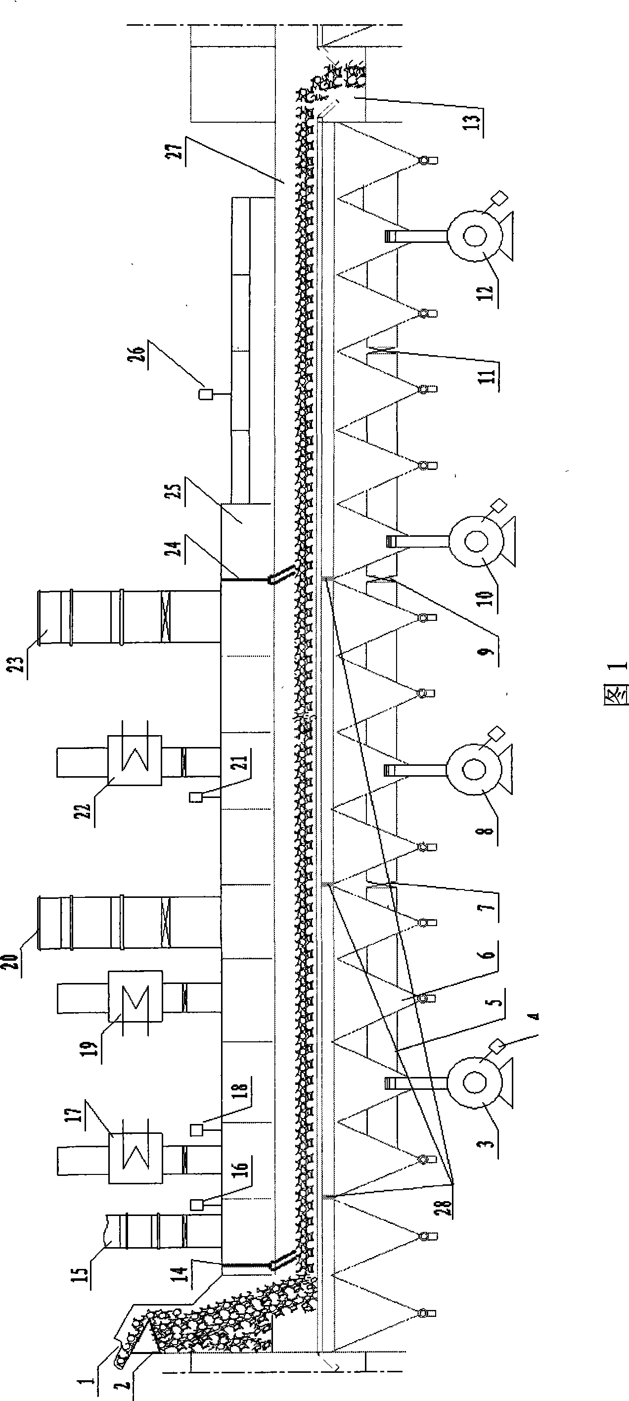
[0034] Technical parameters of sintering cooler:

[0035] 1. Sintering machine: 90m 2

[0036] 2. Cooling machine: 125m 2

[0037] 3. Cooling machine cooling fan: 206,000 m 3 / h, 4 units in total, motor power 355kW

[0038] 4. Mine temperature at the feed inlet of the cooler: average 750°C

[0039] 5 Mine temperature in the upper part of the 11# air box of the cooler: controlled below 200°C

[0040] 6. Mine temperature at the outlet of the cooling machine: controlled below 150°C

[0041] 7. The thickness of the inner material layer of the cooling machine trolley is controlled at 1100±100mm

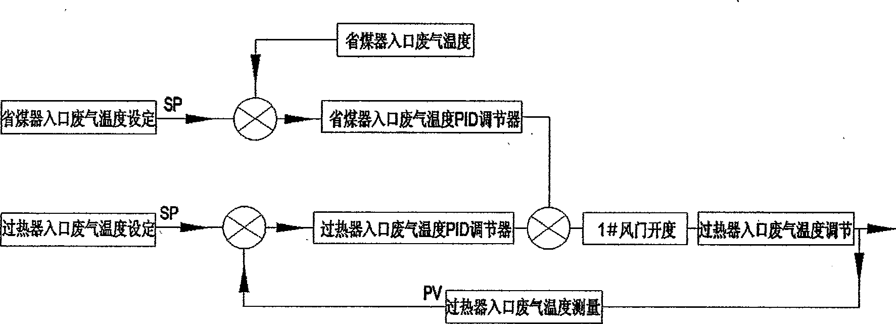
[0042] 8. The exhaust gas temperature at the inlet of the steam superheater is controlled at 450±50°C

[0043] 9. The exhaust gas temperature at the inlet of the economizer is controlled at 210±30...


PUM


Abstract

The invention relates to the field of reclaiming of waste gas and waste heat in the steel industry and power generation by the waste gas and the waste heat, in particular to a control method and a device for stabilizing and improving air taking temperature of a sintered ring in steel smelting. The device and the method are characterized in that the device and the technical method can achieve relative stabilization and moderate improvement of the temperature of the waste gas at the upper part of an inner batch layer of a cooling trolley through increasing and adjusting speed and cooled air of a circular cooler and uniformity for transversely feeding at a feed opening; and at the same time, under the premise that the temperature of the waste gas reaches the technical requirement of a waste heat generating technique, flow of the waste gas at the upper part of the batch layer is increased by properly increasing blown air amount at the lower part of the cooling trolley, so as to ensure relative stabilization and moderate improvement of air inlet temperature and flow of a waste heat boiler, and promote stabilization and improvement of vapor yield of the waste heat boiler and generated energy of a generating system.

Description

technical field [0001] The invention relates to the recovery and utilization of exhaust gas waste heat of sinter coolers in the iron and steel industry, in particular to the field of recovering waste gas waste heat of sinter coolers and using them for power generation. Background technique [0002] In the existing technology of sintering waste heat power generation, the heat source of the waste heat boiler mainly comes from the waste gas waste heat taken from the upper part of the material layer in the cooling zone where the temperature of the sintered ore is cooled by the sinter cooling machine trolley. In the actual working process of sinter cooling, due to the influence of various factors such as sinter flow rate, material layer thickness, air volume at the bottom of the trolley, lateral distribution uniformity of material layer thickness, sinter particle size, etc., the material The exhaust gas temperature on the upper part of the floor tends to fluctuate frequently. At ...

Claims


Application Information

Patent Timeline
IPC IPC(8): F27B21/14F27D19/00F27D17/00G05D23/19G05D23/185
CPCY02P10/25
Inventor 张自意耿佳祥
Owner 昆明阳光基业股份有限公司
Learn More