Turbocharger

A turbocharger and turbine technology, which is applied to machines/engines, gas turbine devices, engine components, etc., can solve the problems of high price, fragile, complex structure, etc. Effect

Inactive Publication Date: 2009-05-13
南通通州江华纺织有限公司
View PDF0 Cites 13 Cited by
  • Summary
  • Abstract
  • Description
  • Claims
  • Application Information

AI Technical Summary

Problems solved by technology

[0003] In order to overcome the deficiencies of the existing turbocharger's fragility, oil leakage and pollution, and overcome the shortcomings of foreign electromagnetic suspension bearing exhaust gas turbochargers, which are expensive, bulky and complex in structure
The invention provides a frictionless turbocharger using a permanent magnet ring to realize the suspension of the turbine rotor shaft. The turbocharger can not only solve the problems of vulnerability, oil leakage and pollution, but also reduce the reaction lag of the turbine , and can be installed arbitrarily, not limited by the installation position and direction; even if it is damaged, it will not have a great impact on the engine except for the power drop

Method used


Image

  • Turbocharger
  • Turbocharger
  • Turbocharger

Examples


Embodiment 1

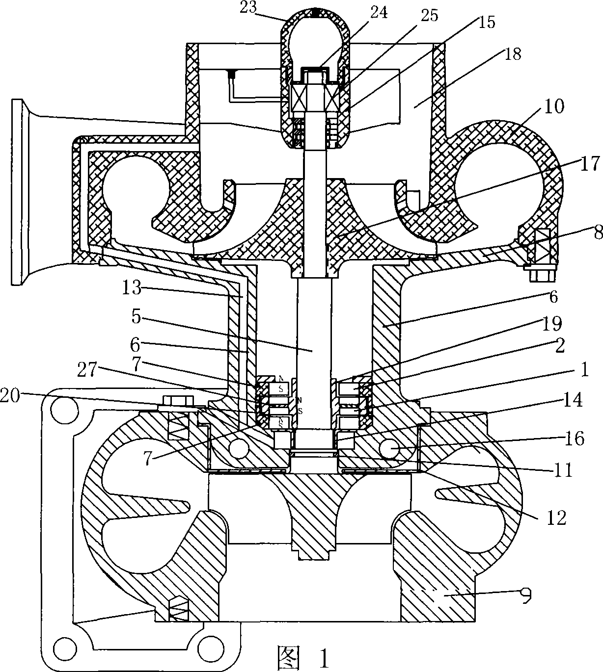
[0024] A kind of turbocharger, as shown in accompanying drawing 1, it comprises turbine rotor shaft assembly 5, intermediate body 6, compressed air impeller 17, turbine casing 9, pressure casing 10, air inlet 18, and pressure casing 1 integral system out of the diffuser plate 8, the turbine rotor shaft assembly 5 includes the rotor shaft, the turbine mounted on the rotor shaft and the compressor impeller 17, on the turbine rotor shaft assembly 5, a set of mutual Cooperating permanent magnet rings, the permanent magnet rings include two permanent magnet moving magnet rings and two permanent magnet static magnet rings, the two permanent magnet moving magnet rings 1 are arranged adjacent to each other, and the two are axially installed There is a magnetic sleeve 27, so that two permanent magnet moving magnet rings are positioned on the non-magnetic sleeve, and a permanent magnet static magnet ring is respectively arranged at the two ends of the permanent magnet dynamic magnet ring...

Embodiment 2

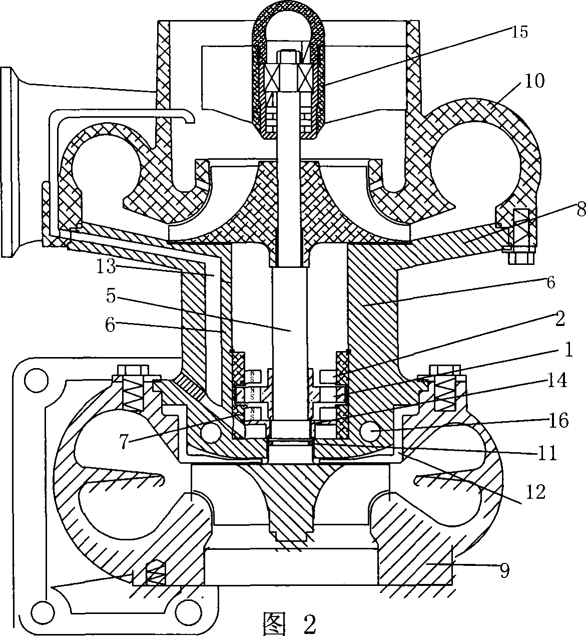
[0029] As shown in Figure 2, the difference between this embodiment and Implementation 1 is that a group of mutually matched permanent magnet rings installed between the turbine and the compressor impeller 17 is an axial polarity permanent magnet ring, which includes A permanent magnet moving magnet ring 1 and two permanent magnet static magnet rings 2, a permanent magnet static magnet ring 2 is arranged on both sides of the permanent magnet moving magnet ring 1, a permanent magnet moving magnet ring 1 and a permanent magnet static magnet ring 2 Cooperate to make the turbine end of the turbine rotor shaft assembly 5 suspend. The specific structure of the cooling method is different, mainly in that the cooling channel 13 makes the compressed air entering the vortex end bearing cavity flow back to the air inlet through the air duct.

Embodiment 3

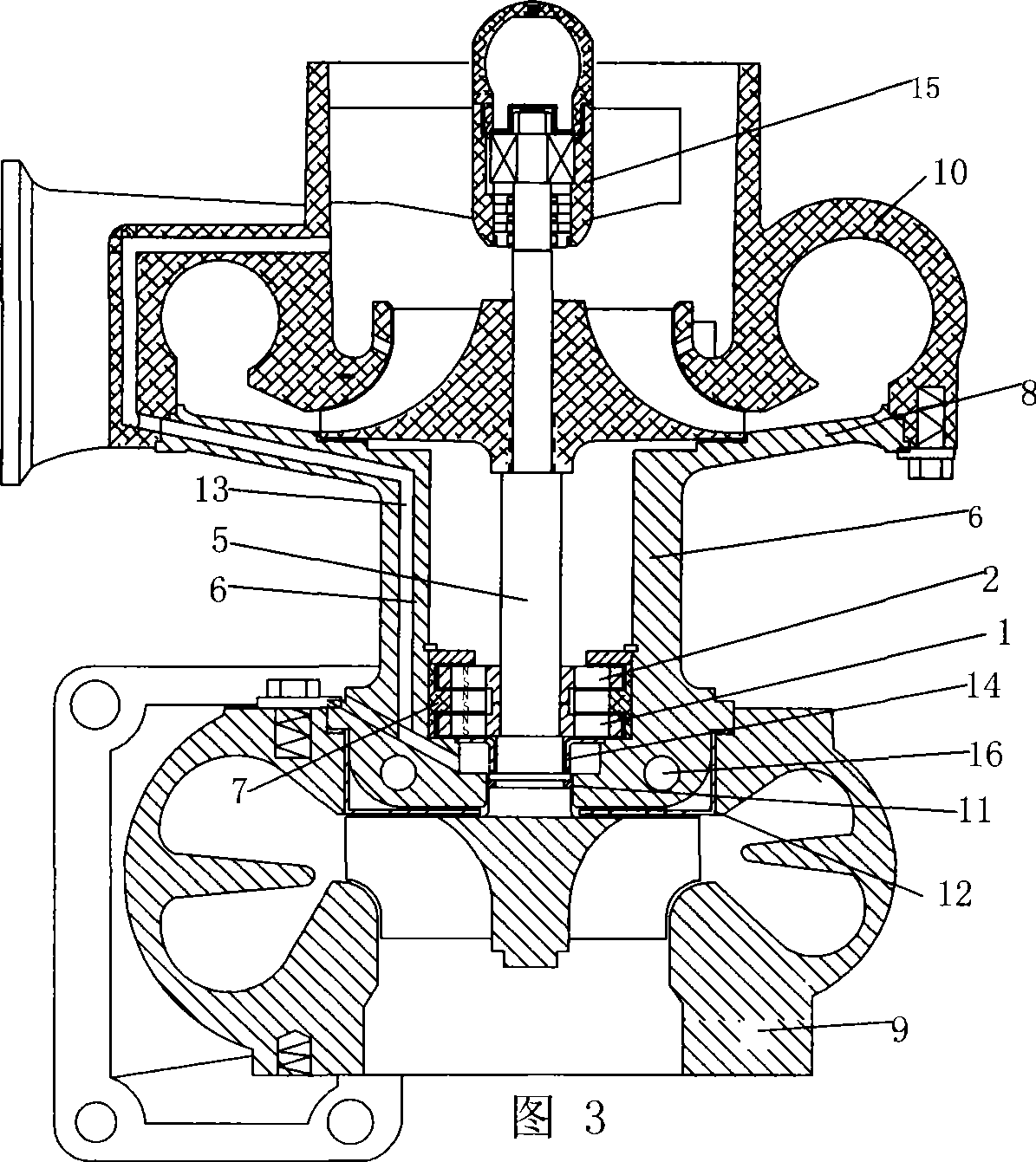
[0031] As shown in Figure 3, the difference between the present embodiment and Implementation 1 is that a group of mutually matched permanent magnet rings installed between the turbine and the compressor impeller 17 is an axial polarity permanent magnet ring, which includes Two permanent magnet moving magnet rings 1 and one permanent magnet static magnet ring 2, the permanent magnet moving magnet ring 1 is located on both sides of the permanent magnet static magnet ring 2 and arranged axially along the rotor shaft.


PUM


Abstract

The invention discloses a turbocharger. The invention adopts a technical proposal that the turbocharger comprises a turbine rotor shaft assembly, an intermediate, a pressure housing, a diffusion plate fixedly connected with or integrally formed with the pressure housing, wherein the turbine rotor shaft assembly is at least provided with a set of permanent magnet rings matched with each other between a turbine and a compressor impeller. The permanent magnet rings comprise at least one permanent magnet dynamic ring and at least one permanent magnet static ring which are matched with each other to suspend a rotor shaft of the turbine rotor shaft assembly. The invention provides a friction-free turbocharger which uses permanent magnet rings to suspend the rotor shaft of the turbine. The turbocharger can solve the problems of susceptibility to damage, oil leakage and pollution, reduce response lags, and does not cause serious influence on the engine except for reduction in power when damaged. The turbocharger solves the problems of susceptibility to damage, oil leakage and pollution of the prior turbocharger and overcomes the drawbacks such as high price, large volume and complex structure of electromagnetic suspension bearing exhaust turbocharger.

Description

technical field [0001] The invention relates to a turbocharger, in particular to a turbocharger which adopts a permanent magnetic suspension bearing and operates at high speed without lubrication. Background technique [0002] At present, the known exhaust gas turbocharger is supported by sliding bearings or ball bearings to position the turbine rotor shaft. When friction and high temperature are generated, a large amount of oil is required to lubricate and cool the bearing system. The friction force aggravates the response lag of the turbine. When the lubricating oil is mixed with impurities and the oil supply is insufficient, the turbocharger is easily damaged. The sealing system relies on piston rings for two-way sealing, that is, sealing oil and sealing gas. For the supercharger used in the diesel locomotive that shares the same oil passage with the engine, when the exhaust gas pressure of the engine crankcase is high, the intake resistance is large, the idling time is ...

Claims


Application Information

Patent Timeline
Patent Type & Authority Applications(China)
IPC IPC(8): F01D25/16F01D25/18F02B37/00F02B39/14F02C6/12
Inventor 陈发谦
Owner 南通通州江华纺织有限公司
Why Eureka
Try Eureka