
Production method for Sm(Co,M)7 type alloy thin strip magnet

A technology of thin strips and magnets, applied in the direction of magnetic objects, inductance/transformer/magnet manufacturing, magnetic materials, etc., can solve the problems of reducing the pinning effect, and achieve the effect of high cost performance in the market, adjustable length and diameter, and low density

Inactive Publication Date: 2009-05-13
HEBEI UNIV OF TECH
View PDF2 Cites 9 Cited by
  • Summary
  • Abstract
  • Description
  • Claims
  • Application Information

AI Technical Summary

Problems solved by technology

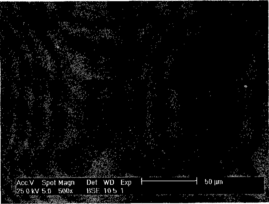
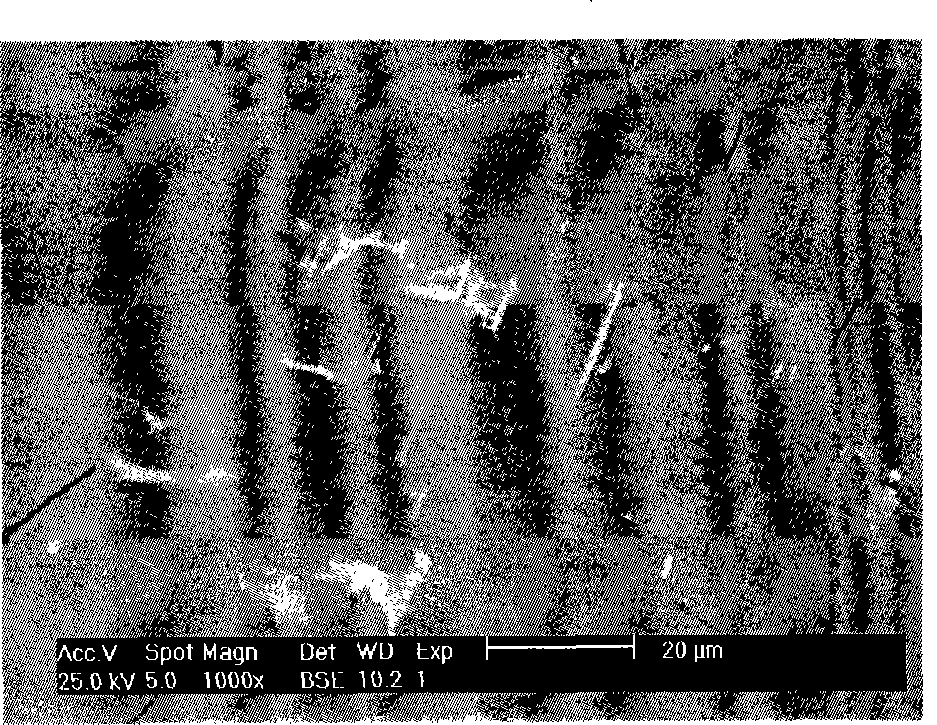
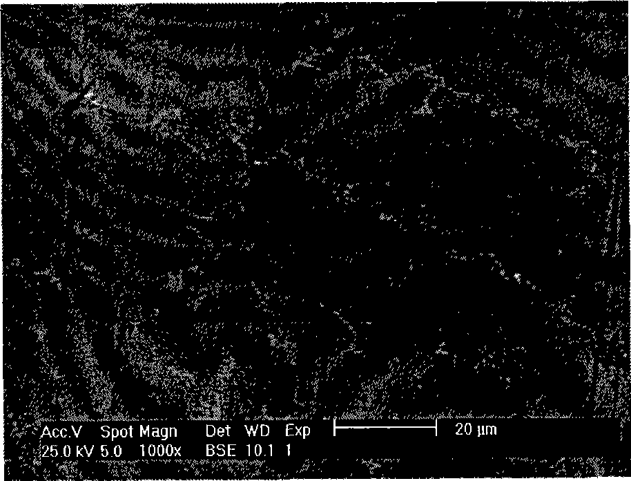
Taiwan Chang et al., although tried in Sm(Co, Hf) 7 Adding small-sized C atoms into the type alloy, try Figure 1 On the one hand, the grains are refined, and on the other hand, a pinning phase is obtained to obtain high magnetic properties, but the actual result is that the directly added C element forms a non-magnetic Sm 2 C 3 , greatly reducing the pinning effect

Method used


Image

  • Production method for Sm(Co,M)7 type alloy thin strip magnet
  • Production method for Sm(Co,M)7 type alloy thin strip magnet
  • Production method for Sm(Co,M)7 type alloy thin strip magnet

Examples


Embodiment 1

[0029] The first step, raw material preparation

[0030] According to the ratio of raw materials SmCo 6.9 f 0.1 (CNT) 0.05 , take raw material pure Sm, pure Co, pure Hf and CNT, add 5% pure Sm of the mass percentage of the pure Sm that weighs pure Sm according to raw material ratio more when batching to compensate the loss that volatilization causes during smelting, CNT is market Sales of multi-walled carbon nanotubes with a diameter of 1nm-60nm, a length of 5nm-50μm, and a purity higher than 60%, thereby completing the preparation of raw materials.

[0031] The second step is to melt the raw materials to prepare master alloy ingots

[0032] Put all the raw materials prepared in the first step into the crucible of the vacuum electric arc furnace, and evacuate the furnace body to 10 -3 Pa, the temperature of the furnace rises to higher than the melting point of the raw metal Hf, until all the raw metals are smelted evenly, and the carbon nanotubes are evenly distributed, an...

Embodiment 2

[0041] Except that the circumferential speed rotation of the cooling molybdenum roll wheel of the third step in embodiment 1, that is, the rapid quenching speed of the melt, becomes 20m·s -1 Except, others are all the same as embodiment 1.

Embodiment 3

[0043] Except that the circumferential speed rotation of the cooling molybdenum roll wheel of the third step in embodiment 1, that is, the rapid quenching speed of the melt, becomes 30m·s -1 Except, others are all the same as embodiment 1.


PUM

PropertyMeasurementUnit
thicknessaaaaaaaaaa
particle sizeaaaaaaaaaa
diameteraaaaaaaaaa

Abstract

The invention provides a preparation method used for Sm(Co, M)7 typed alloy ligature magnet, belonging to the magnet technical field of hard magnetic material containing rare earth metal and magnetic transition metal. The preparation method comprises the steps as follows: the molecular formula of the fuse is SmCo<7-x>Mx(CNT)y; wherein, M is Hf, Ga or Si; CNT is carbon nano-tube; according to the atom percentage, the symbols which limits the composition meets the following formulas: x is not less 0.05 and not more than 1.6; y is not less than 0.01 and not more than 0.1; the fuse is rapidly quenched on a cooling molybdenum roller wheel or a copper roller wheel which rotates at a circumferential velocity of 10-60m / s, thus preparing the Sm(Co, M)7 typed alloy ligature magnet which has the mass magnetization intensity of 40.0-105.0Am<2> / kg, has the intrinsic coercivity of 480.0-1840.0kA / m after being magnetized in an external magnetic field of 4.8MA / m, has the intrinsic coercivity of 480.0-2,000.0kA / m after being magnetized in an external magnetic field of 7.2MA / m, has the thickness of 20-120 microns and has the average grain size of 10-200nm. The carbon nano-tube which is used as an ideal pinning phase stabilizes the phase structure of the Sm(Co, M)7 typed alloy ligature magnet when in a quick quenching state and a heat disposal state, optimizes the micro-structure of the grain size and leads the alloy to be practical permanent magnet with high coercivity.

Description

technical field [0001] The technical scheme of the present invention relates to the magnet of hard magnetic material containing rare earth metal and magnetic transition metal, specifically Sm(Co, M) 7 The preparation method of alloy strip magnet. Background technique [0002] In the field of magnet technology, the use of transition group rare earth alloys has successfully developed SmCo 5 Type alloy, Sm 2 co 17 type alloy and Nd-Fe-B type alloy three-generation permanent magnet. It was recently discovered that with TbCu 7 SmCo 7 type alloys exhibit a large anisotropy field (H A =7.960-22.3MA·m -1 ) and low temperature coefficient of intrinsic coercive force (β=-0.11%) and other high-temperature excellent properties. SmCo 7 The composition of the type alloy lies in the SmCo 5 type alloy and Sm 2 co 17 Between type alloys, the space group is P6 / mmm. SmCo 7 The ratio of saturation magnetization to Curie temperature of type alloy Sm 2 co 17 Type alloys are lower,...

Claims


Application Information

Patent Timeline
Patent Type & Authority Applications(China)
IPC IPC(8): H01F1/047H01F1/06H01F41/02C22C1/03
Inventor 孙继兵崔春翔韩丹杨薇韩瑞平
Owner HEBEI UNIV OF TECH
Learn More