Safety monitoring system and method for circumference

A technology for safety monitoring and monitoring systems, applied in signal transmission systems, non-electrical signal transmission systems, measuring devices, etc., can solve problems such as signal blanking, difficulty in effective work, and inability to perform real-time monitoring, achieving high sensitivity and low cost. low effect

Inactive Publication Date: 2009-06-24
SUZHOU GUANGLAN INFORMATION TECH
View PDF1 Cites 24 Cited by
  • Summary
  • Abstract
  • Description
  • Claims
  • Application Information

AI Technical Summary

Problems solved by technology

Its essence is light radar technology, which is to judge the disturbance of the optical fiber and locate it by sending narrow light pulses into the optical fiber and detecting the Rayleigh scattering and Fresnel reflection signals generated in the optical fiber, but the disadvantage is that the signal noise is too large , the signal processing time is long, and real-time monitoring cannot be carried out, so the practical significance is not great
This invention is a breakthrough for the safety monitoring technology of large-scale perimeter, but the disadvantage is that the optical path system in this invention is u

Method used


Image

  • Safety monitoring system and method for circumference
  • Safety monitoring system and method for circumference
  • Safety monitoring system and method for circumference

Examples


Embodiment Construction

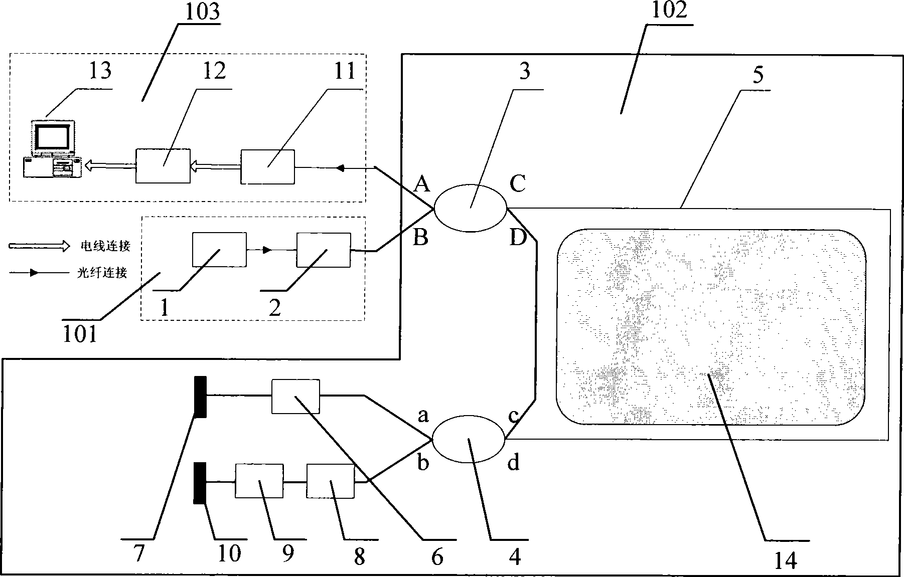
[0020] In this embodiment, the model of the laser light source 1 is SXSLED1501-FOS, the 3dB bandwidth is 50nm, the output power is 2mw, and the center wavelength is 1310nm or 1550nm. This is a continuous superradiant laser diode. Optical isolator 2 type: 1550nm polarization independent type. Beam splitters 3 and 4 are single-mode beam splitters with primary taper 2×2, and the splitting ratio is 1:1. Mirror 7 and 10 models: aluminized coating, 95% reflectivity at 1550nm. Phase Modulator 6 and 8 Model: PZ1-STD-FC / APC. Sensing fiber 5 and transmission fiber model: Corning-SMF-28. Photodetector 11 model: InGaAs-PIN-1550, saturation power 2mw. Data collector 12 model: NI PCI-6122. Computer 13 Model: Advantech Industrial Computer IPC-610-H.

[0021] Such as figure 1 As shown, the perimeter security monitoring system includes an optical path system 101 , an optical fiber sensing system 102 , and a monitoring system 103 . Wherein, the optical system 101 includes a laser light ...


PUM

PropertyMeasurementUnit
Center wavelengthaaaaaaaaaa

Abstract

The invention discloses a perimeter security monitoring system. A light source, an optical isolator and a port B of a beam splitter 3 are connected through an optical fiber in sequence, the beam splitter 3 is connected with a beam splitter 4 through a sensing optical fiber, the port a of the beam splitter 4 is connected with a reflecting mirror through a phase modulator, the port b of the beam splitter 4 is connected with a delay winding through the phase modulator, and the delay winding is connected with the reflecting mirror. When the sensing optical fiber vibrates along the line, the two paths of interference optical signals carried with the same vibration information reach an photoelectric detector from the port A of the beam splitter 3, the analog signal is transformed into a digital signal through a data acquisition unit, the digital signal is transmitted to a computer, and the positioning of a vibration source is obtained by a formula, i.e. z is equal to LD*phi s(t)/phi M-Z (t). The invention can monitor the perimeter vibration conditions at real time, has very high sensitivity and positioning accuracy and reliably runs.

Description

technical field [0001] The invention relates to the field of public security protection, in particular to a perimeter security monitoring system and a perimeter security monitoring method using the system. Background technique [0002] In recent years, with the development of optical fiber sensing technology, long-distance distributed optical fiber sensing technology has also begun to be applied to perimeter security monitoring. Compared with the traditional perimeter security system, the fiber optic perimeter security system is a non-destructive security system, which has the advantages of anti-electromagnetic interference, corrosion resistance, strong concealment, low power consumption, and long life. [0003] Aiming at the problems existing in the existing perimeter security monitoring technology, an attempt is first made to implement perimeter security monitoring by using OTDR (Optical Time Domain Reflectometer, Optical Time Domain Reflectometer) technology. Its essence...

Claims


Application Information

Patent Timeline
IPC IPC(8): G08C23/06G01M11/00
Inventor 陈玉凤
Owner SUZHOU GUANGLAN INFORMATION TECH
Why Eureka
Try Eureka