Stuffing with wing veins for biological treatment of exhaust gas

A technology for biological treatment and waste gas, applied in sustainable biological treatment, biological water/sewage treatment, chemical/physical processes, etc., can solve the problems of difficult biofilm blockage, microbial film hanging easily, and high pollution load, and achieve easy film hanging. , the effect of large biomass and high pollution load

Inactive Publication Date: 2009-07-08
ZHEJIANG UNIV OF TECH +1
View PDF7 Cites 10 Cited by
  • Summary
  • Abstract
  • Description
  • Claims
  • Application Information

AI Technical Summary

Problems solved by technology

[0006] In order to solve the above-mentioned shortcomings of the existing chemical fillers applied to waste gas treatment biological fillers, the present invention proposes a waste gas biologic

Method used


Image

  • Stuffing with wing veins for biological treatment of exhaust gas
  • Stuffing with wing veins for biological treatment of exhaust gas
  • Stuffing with wing veins for biological treatment of exhaust gas

Examples


Embodiment 1

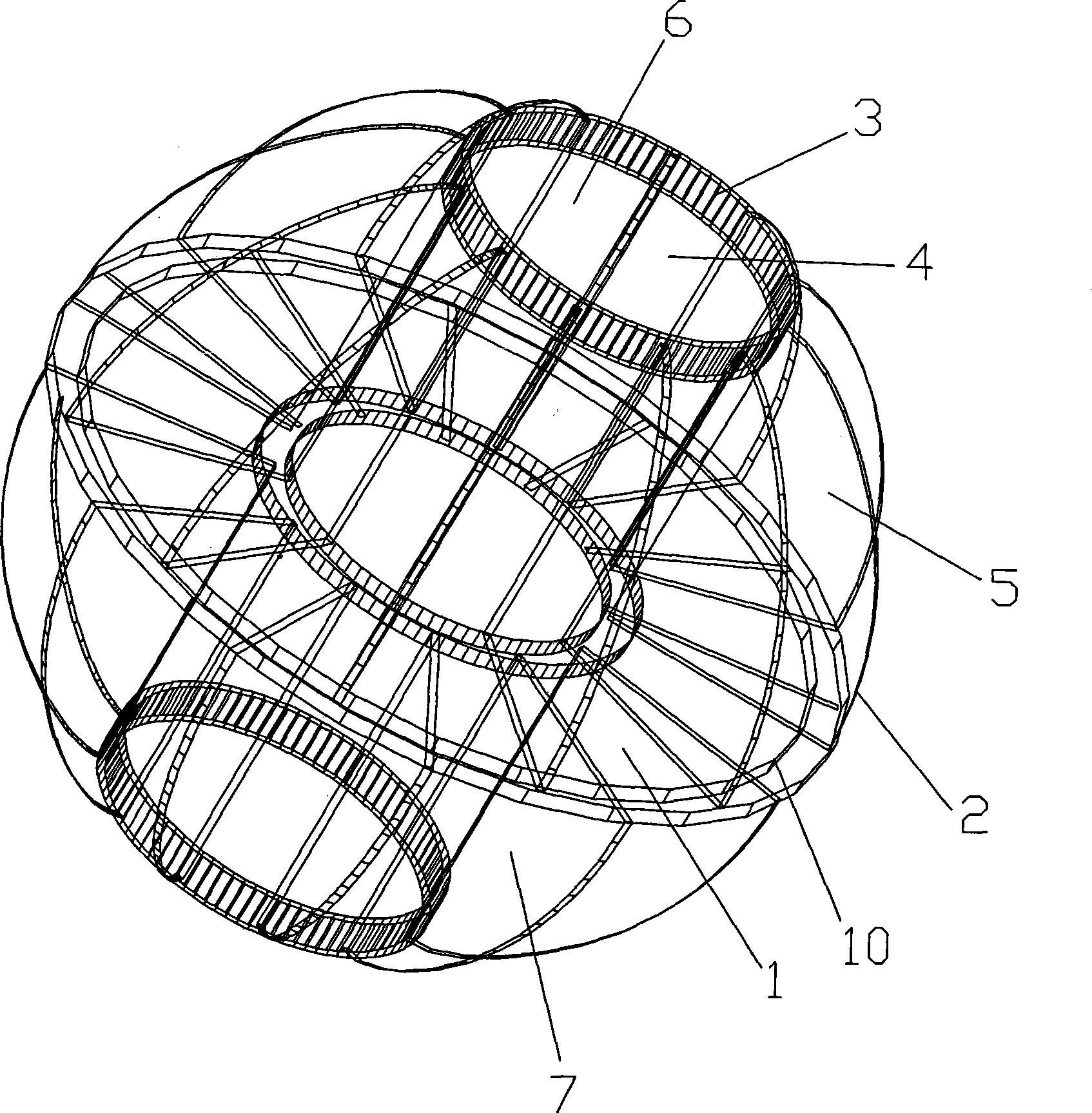
[0034] refer to Figure 1-3 : A kind of corrugated multi-faceted ball filler for waste gas biological treatment, the filler is surrounded by two hemispheres to form a grid body whose outer contour surface is a spherical surface, the butt surface of the two hemispheres constitutes the equatorial plane 1, and the equatorial plane 1 The outer ring is the equatorial ring 2; each of the hemispheres is provided with a latitude ring 3 parallel to the equatorial ring 2, and the plane where the latitude ring 3 is located is the latitude plane 4, between adjacent latitude planes 4 or the equatorial plane 1 Between the adjacent latitudinal planes 4 are connected blades 5 divergently distributed around the axis of the hemisphere, and the edges of the blades 5 are supported between adjacent latitudinal planes 4 or between the equatorial plane 1 and its adjacent latitudinal planes 4 , the outer arc edge forms the outer contour line of the sphere, and the grid unit 7 is formed between the ad...

Embodiment 2

[0057] refer to Figure 4-6 : A corrugated wing multi-face column filler for waste gas biological treatment, the filler is composed of an upper column 8 and a lower column 9. The outer contour surface is a cylindrical grid body, and the butt surface of the upper column and the lower column Constitute the equatorial plane 1, the outer ring of the equatorial plane 1 is the equatorial ring 2; one of the upper and lower cylinders is provided with at least one latitude ring 3 parallel to the equatorial ring 2, and the plane where the latitude ring 3 is located is the latitude plane 4. Between the adjacent latitude planes 4 or between the equatorial plane 1 and its adjacent latitude plane 4, there are blades 5 divergently distributed around the axis, and the edges of the blades 5 are supported between the adjacent latitude planes 4 or the equator Between the surface 1 and its adjacent latitude surface 4, its outer edge constitutes a cylindrical side, and a grid unit 7 is formed betw...


PUM


Abstract

The invention relates to a packing with raised grain for biologically treating waste gas. The packing is a grille body of which the external outline surface is a spherical surface enclosed by two hemispheres; the binding surface of the two hemispheres forms an equatorial surface; the outer ring of the equatorial surface is an equatorial ring; each of the hemispheres is provided with at least one latitude ring in parallel with the equatorial ring; a plane which is provided with the latitude ring is a latitude plane; blades divergently distributed around the axes of the hemispheres connect adjacent latitude planes or the equatorial plane and the adjacent latitude plane thereof; the edges of the blades are supported between the adjacent latitude planes or the equatorial plane and the adjacent latitude thereof, and the external circle-arc edges thereof form the external outline of the sphere; grille units are formed by the adjacent blades; the blades are provided with a rough surface facilitating the mounting of microorganism; the packing is provided with a through channel along the axes of the two hemispheres; the inner surface of each grille unit opposing to the external outline surface thereof form the outer edge of the channel.

Description

technical field [0001] The invention relates to a packing used for biological treatment of waste gas, in particular to a packing used in a biological trickling filter bed of a waste gas biological treatment device. Background technique [0002] Because of its large biomass and controllable growth conditions of microorganisms, the biological trickling filter bed is a highly efficient reactor in the waste gas biological treatment device. Therefore, it is required that the biological filler used has sufficient specific surface area and sufficient gaps and channels, which can not only facilitate the attachment and growth of active microorganisms, but also facilitate the shedding of aged biofilms to flow away through the filler gap. [0003] Since biological waste gas treatment is a new technology in recent years, most of the fillers currently used are replaced by traditional chemical fillers, such as Pall rings and Raschig rings of various materials, often because the specific s...

Claims


Application Information

Patent Timeline
IPC IPC(8): B01J19/30B01D53/84C02F3/10
CPCY02A50/20Y02W10/10
Inventor 陈建孟王家德王毓仁周珍雄孙永强
Owner ZHEJIANG UNIV OF TECH
Why Eureka
Try Eureka