Double-cladding optical fiber temperature sensor

A temperature sensor, double-clad optical fiber technology, used in thermometers, thermometers with physical/chemical changes, instruments, etc., can solve the problems that optical fiber temperature sensors cannot be widely used, cannot directly interpret sensing data, and demodulate signals. High cost , to achieve the effect of simple structure, flexible design and low cost

Inactive Publication Date: 2009-07-15
SOUTH CHINA UNIV OF TECH
View PDF0 Cites 3 Cited by
  • Summary
  • Abstract
  • Description
  • Claims
  • Application Information

AI Technical Summary

Problems solved by technology

In the distributed optical fiber temperature sensing technology based on Raman scattering and Brillouin scattering, and the optical fiber temperature sensing technology based on Bragg grating and fluorescence measurement, it is necessary to restore and fuse the sensor data, which cannot directly interpret the sensing data, making Demodulating the signal is expensive
In short, high application cost is one of the main reasons why fiber optic temperature sensors cannot be widely used

Method used


Image

  • Double-cladding optical fiber temperature sensor
  • Double-cladding optical fiber temperature sensor
  • Double-cladding optical fiber temperature sensor

Examples


Embodiment 1

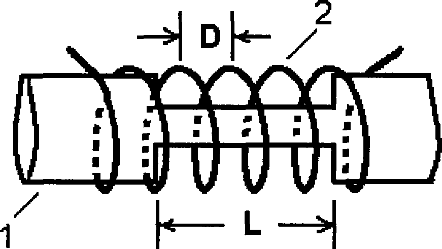
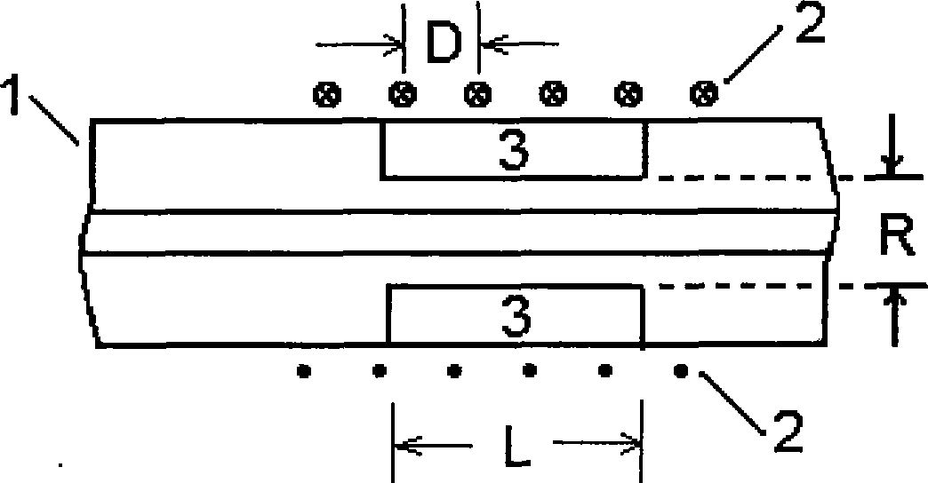
[0016] The structure of the present invention is as figure 1 and figure 2 shown by figure 1 and figure 2 It can be seen that the step-type optical fiber 1 adopts Corning SMF-28e. The length of the sensing section in the optical fiber 1 is L as shown in the figure, and the outer diameter of the inner cladding is R as shown in the figure. A metal wire with a diameter of 0.13mm is wound into a solenoid 2, the pitch D of which is 0.3mm, and its inner diameter is slightly larger than the outer diameter of the optical fiber 1, so that the optical fiber 1 can just pass through it, and its length is greater than L, which is taken in this embodiment 9mm. The outer cladding layer 3 is made of polymer material OE-4110 produced by Dow Corning Company. Its thermo-optic coefficient is equal to 0.0003, and its refractive index for a wavelength of 1554nm is 1.4600 at a temperature of 22°C. Using the table-top stabilized light source, table-top optical power meter, and digital electroni...

Embodiment 2~4

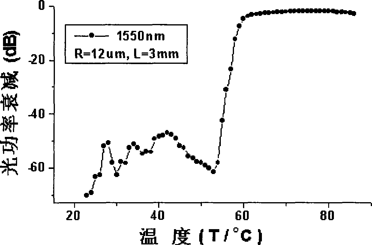
[0020] The difference from Example 1 is that the outer diameters of the inner cladding are respectively 13 μm, 16 μm and 20 μm, and the others are the same as in Example 1. The experimental curves of these 3 embodiments for the optical power loss of 1550nm wavelength as a function of temperature are shown in Figure 5 middle. The ranges of the steep loss change regions corresponding to Embodiments 2 to 4 are: -50dB, -43dB and -7dB respectively. From Figure 5 It can also be seen from the figure that the minimum optical power loss (ie, insertion loss) corresponding to Embodiments 2 to 4 are: -3.8dB, -1.7dB and -1.5dB, respectively. It can be seen from these two sets of data that the smaller the outer diameter of the inner cladding, the larger the range of the steep change region of optical power loss and the greater the insertion loss.

Embodiment 5

[0022] The difference from Example 1 is that the length of the sensing section is 5.6 mm, the outer diameter of the inner cladding is 13 μm, and the others are the same as in Example 1. The experimental curve of the sensor of this embodiment for the optical power loss of 1550nm wavelength as a function of temperature is shown in Figure 6 middle. The scope of the steep loss change region of this embodiment is the same as that of embodiment 2. It can be seen that, when the length of the sensing section is changed from 3mm to 5.6mm, and other things are the same as in Embodiment 1, the range of loss variation remains unchanged.


PUM

PropertyMeasurementUnit
lengthaaaaaaaaaa
lengthaaaaaaaaaa
refractive indexaaaaaaaaaa

Abstract

The invention discloses a double cladding optical fiber temperature sensor, which comprises a double cladding sensing segment with length of 2-6mm consisted of a fiber core, an inner cladding and an outer cladding on the step type optical fiber and a device for fixing the outer cladding; the inner cladding of the sensing segment with outer diameter of 11-20um is formed by partly eating off the original cladding; and the outer cladding is formed by coating polymer material on the inner cladding. Compared with the current optical fiber sensors, the invention not only has the advantages of good insulating property and electromagnetic interference prevention, but also has the advantages of simple structure, low manufacturing cost and low signal acquisition and conversion cost; moreover, under a certain condition, while the environment temperature changes for 10 degrees centigrade, the light power output by the sensor can change for -50dB; therefore, the invention is especially suitable for temperature alarm, can be widely used for remote temperature sensing and alarming in the places of petroleum producing, processing and storing, transformer station and inner part of large scale transformer.

Description

technical field [0001] The invention relates to a device for long-distance temperature sensing using an optical fiber, in particular to a temperature sensing method using a double-clad optical fiber structure and its application in temperature alarming. Background technique [0002] Optical fiber temperature sensor has become one of the leading directions of sensing technology due to its unique advantages such as strong anti-electromagnetic interference ability and good insulation performance. The detection techniques used in fiber optic temperature sensors mainly include: interferometry, Raman scattering, Brillouin scattering, Bragg grating and fluorescence measurement. Among the interferometry methods, the Fabry-Perot fiber optic temperature sensor is currently the most widely used, but the output light intensity signal of the sensor is very weak, so it requires high-cost signal acquisition and processing technology; the interferometry using the Mach-Zehnder structure Thi...

Claims


Application Information

Patent Timeline
Patent Type & Authority Applications(China)
IPC IPC(8): G01K11/32
Inventor 张小康叶晓靖
Owner SOUTH CHINA UNIV OF TECH
Why Eureka
Try Eureka