
Zero point calibration method and its use in optical micro-scanning micro-thermal imaging system

A technology of micro-scanning and optical flat panel, which is applied in the field of scanning zero, can solve the problems that the spatial resolution of the system cannot be improved, the design of the optical flat-panel micro-scanning system falls short, and the quality is poor, so as to improve efficiency and reliability, light weight, The effect of low power consumption

Inactive Publication Date: 2009-07-22
BEIJING INSTITUTE OF TECHNOLOGYGY
View PDF0 Cites 20 Cited by
  • Summary
  • Abstract
  • Description
  • Claims
  • Application Information

AI Technical Summary

Problems solved by technology

[0006] However, in the flat-panel rotating micro-scanning micro-thermography system, no matter after system installation or detection, since the azimuth angles of the thermal imaging components are not completely consistent each time, it is necessary to perform a new adjustment for the zero point (angle) position of the 2×2 micro-scan Calibration, otherwise the micro-displacement position of the four images collected deviates from the standard 2×2 micro-scanning cube, the quality of the image reconstructed by oversampling is worse than that of bilinear amplification, and the design of the optical flat-panel micro-scanning system falls short. The spatial resolution of the

Method used


Image

  • Zero point calibration method and its use in optical micro-scanning micro-thermal imaging system
  • Zero point calibration method and its use in optical micro-scanning micro-thermal imaging system
  • Zero point calibration method and its use in optical micro-scanning micro-thermal imaging system

Examples


Embodiment

[0091] 1. Micro-scanning zero-point calibration of the actual optical micro-scanning micro-thermal imaging system

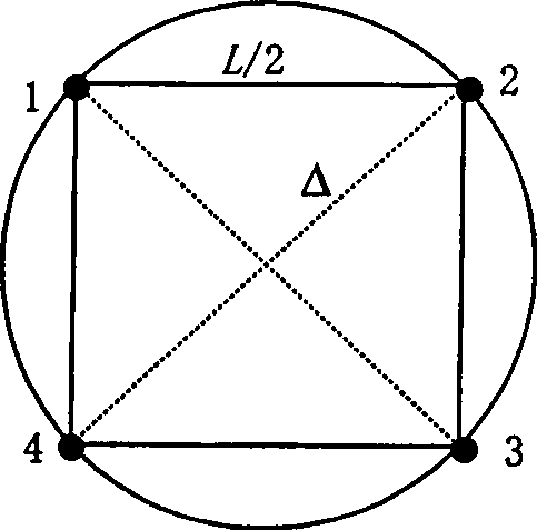
[0092] The zero-point calibration of the actual micro-thermography system is carried out by using the above-mentioned micro-scanning zero-point calibration method. Figure 9 The micro-displacement positions of four low-resolution images collected in the standard 2×2 micro-scan mode before and after micro-scanning zero point calibration are given, and the coordinate unit in the figure is 1 unit pixel. It can be seen that after micro-scanning zero-point calibration, the low-resolution image acquisition position is significantly closer to the upright regular quadrilateral than before calibration, which shows the effectiveness of the micro-scanning system zero-point calibration method.

[0093] Of course, due to the inevitable error factors such as mechanical vibration and environment in actual processing, assembly and system work, the micro-displacement positions of...


PUM


Abstract

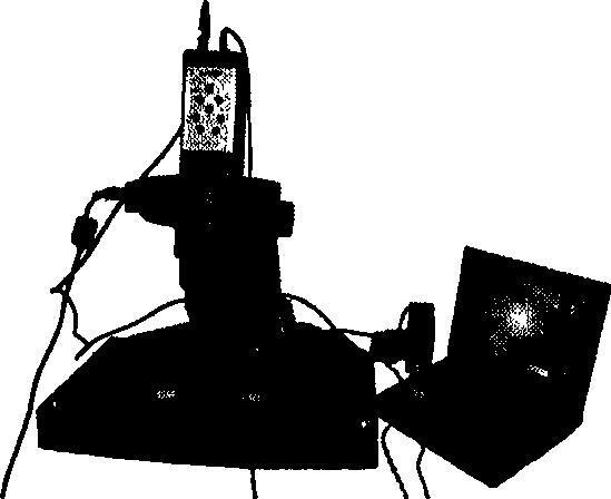
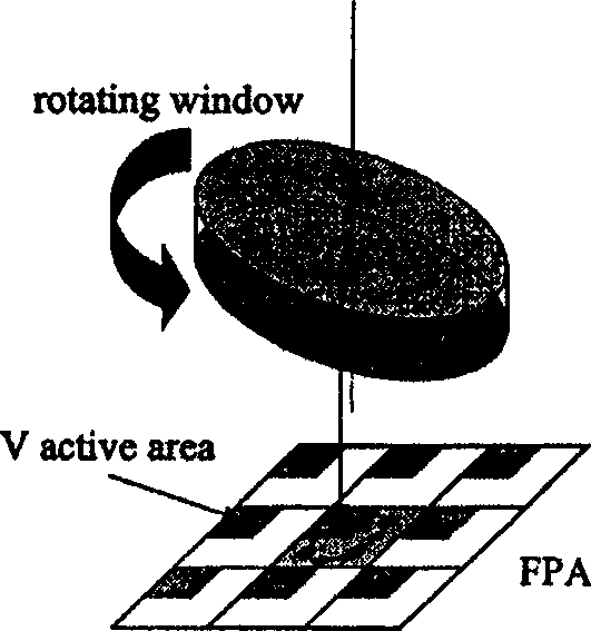
The invention relates to a zero point calibration method and the application in an optical micro scanning micro thermal imaging system thereof, belonging to the infrared thermal imaging field. The method is as follows: firstly, two images are collected by taking the testing zero point of a rotating platform as a starting point; and then the micrometric displacement between the two images is calculated by using an improved frequency domain image registration algorithm; the rotating angle and direction is determined by a micro zero point calibration method according to the micrometric displacement; the rotating platform is controlled to rotate a corresponding angle to reach the zero point position of optical micro scanning of the system. And then four under sampling and low resolving power images are collected according to a standard 2*2 micro scanning mode and over-sampling images, the resolving power of which is increased by one time, are obtained by directly interpolation according to a mode of collecting images. As a micro scanner device of a monoblock infrared parallel plate, hardware with high positioning accuracy, fast speed and being apt to the system, and a real time implementation processed micro scanning zero point calibration method are adopted, the resolving power of the space of the system is obviously increased, thus promoting the application of micro thermal imaging technique in multiple fields.

Description

technical field [0001] The invention relates to a micro-scanning zero-point calibration method for an optical flat plate rotating micro-scanning micro-thermography system, which belongs to the field of infrared thermal imaging, can solve the key problem of the practicality of the developed optical micro-scanning micro-thermography system, and improve the system performance. Spatial resolution, the optical micro-scanning micro-thermal imaging system can be used in microelectronic chip and its circuit design and fault detection, biomedical micro-thermal imaging analysis, scientific research and other fields, providing technical means for high-resolution micro-thermal analysis. Background technique [0002] Thermal imaging technology has been widely used in industrial testing, medical diagnosis and scientific research, and has become an effective thermal diagnostic tool. However, most thermal imaging systems currently work in the telephoto mode, which is not suitable for applic...

Claims


Application Information

Patent Timeline
IPC IPC(8): G01N25/72G01N25/00G01N33/48G01R31/303A61B5/00H04N1/047
Inventor 高美静金伟其王霞王岭雪于杰刘广荣
Owner BEIJING INSTITUTE OF TECHNOLOGYGY
Learn More