A charge pump circuit

A technology of charge pump and circuit, applied in the field of electronics

Inactive Publication Date: 2009-07-22
CHENGDU CORPRO TECH CO LTD
View PDF0 Cites 23 Cited by
  • Summary
  • Abstract
  • Description
  • Claims
  • Application Information

AI Technical Summary

Problems solved by technology

However, due to the existence of parasitic capacitances C1 and C2, when the switch is turned off, c1 will still charge node A to VDD, and c2 will discharge node B to VSS, and the capacitor charge sharing effect still exists

Method used


Image

  • A charge pump circuit
  • A charge pump circuit
  • A charge pump circuit

Examples


Embodiment Construction

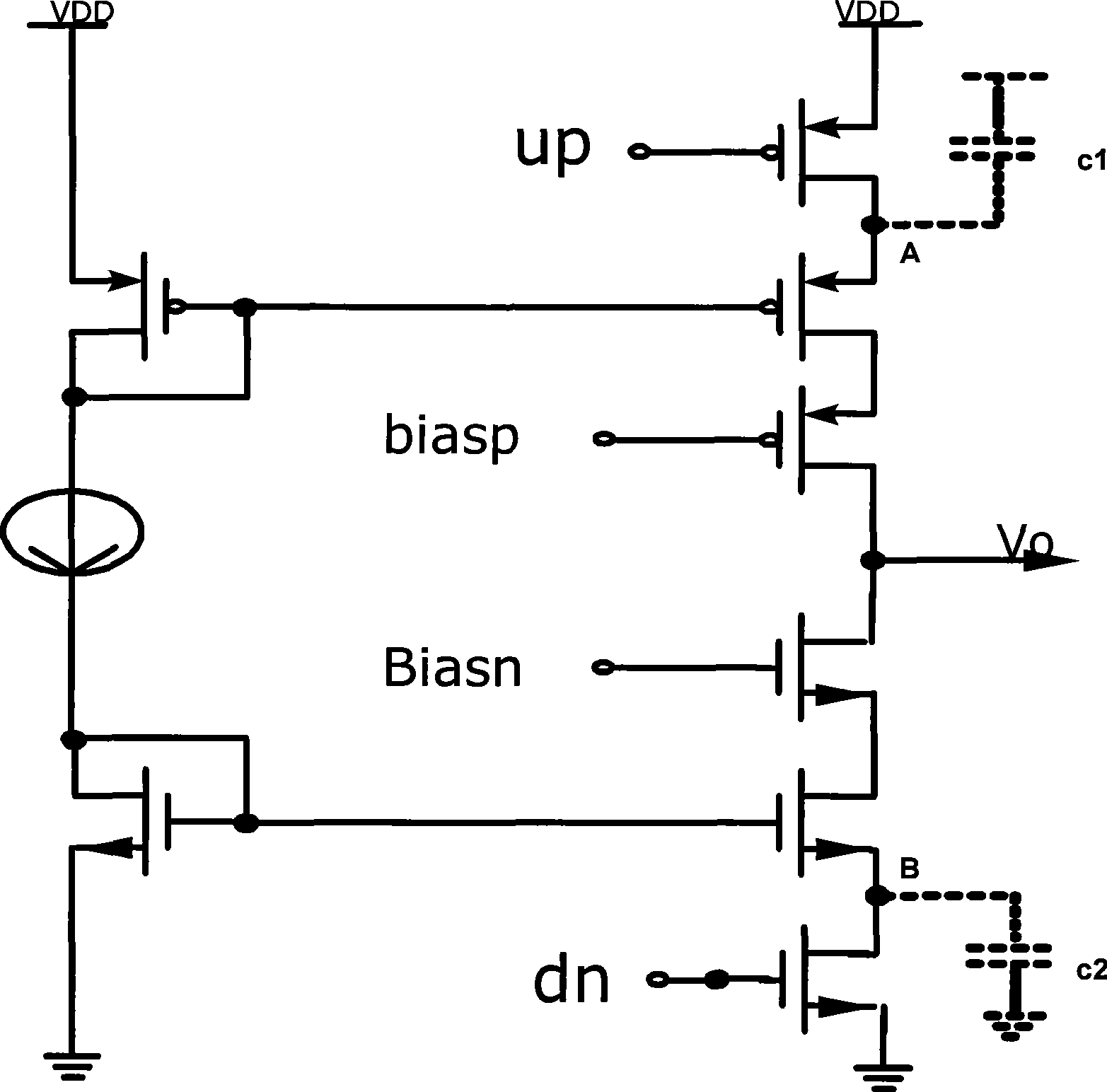
[0018] The charge pump circuit according to the present invention includes an input high-swing cascode current mirror, an output high-swing cascode current mirror, a suppression charge sharing circuit, wherein the pull-up in the output high-swing cascode current mirror The output cascode current mirror and the pull-down output cascode current mirror together with the suppressing charge sharing circuit, the pull-up switch tube and the pull-down switch tube form the pull-up and pull-down circuits. The pull-up circuit provides a pull-up current to boost the charge pump output voltage. The pull-down circuit provides a pull-down current to reduce the charge pump output voltage. The output high-swing cascode current mirror increases the output resistance, better matches the current and minimizes the sensitivity of the output current to the output voltage. The charge sharing suppression circuit includes a first control circuit and a second control circuit, both of which can reduce t...


PUM


Abstract

The invention discloses a charge pump circuit which comprises an input high swing amplitude cascode current mirror, an output high swing amplitude cascode current mirror and a suppression charge shared circuit, wherein, a pull-up and a pull-down circuits are formed by a pull-up output cascode current mirror and a pull-down output cascode current mirror in the output high swing amplitude cascode current mirror as well as the suppression charge shared circuit, a pull-up switch pipe and a pull-down switch pipe. The cascode current mirror structure is adopted by output, so that the resistance of the output current mirror is increased, the influence of the change of the output voltage on the electric current is reduced, and the noise of a switching tube is avoided affecting the output voltage. Meanwhile, the sharing effect and the coupling effect of the charge can be inhibited.

Description

technical field [0001] The invention relates to the field of electronic technology, in particular to a charge pump circuit used by a phase-locked loop. Background technique [0002] Many traditional digital signal transmission, processing and digital-analog hybrid circuits require precise clock signals. Phase-locked loops are a wide range of circuits used to generate precise clock signals based on reference clocks, frequency synthesizers, frequency multipliers and clock Restoration circuits, etc. are examples of frequency control using phase-locked loops. [0003] figure 1 It is a typical phase-locked loop circuit, which includes a phase detector 101 , a charge pump 102 , a loop filter 104 , a voltage-controlled oscillator 106 and a frequency divider 107 . Wherein the phase detector 101 is used to compare the value of the input reference clock signal fref and the output clock signal fb from the frequency divider 107, and output a pull-up signal UP or a pull-down signal DN ...

Claims


Application Information

Patent Timeline
Patent Type & Authority Applications(China)
IPC IPC(8): H02M3/10H03L7/085
Inventor 唐俊
Owner CHENGDU CORPRO TECH CO LTD
Why Eureka
Try Eureka