A vacuum magnetron sputtering coil coating device

A vacuum magnetron sputtering and coating device technology, applied in sputtering coating, vacuum evaporation coating, ion implantation coating, etc., can solve problems such as uneven vacuum degree, low work efficiency, oil return from oil diffusion pump, etc. , to achieve the effect of ensuring peel strength, improving work efficiency and improving roughness

Active Publication Date: 2012-02-01
GUANGZHOU FANGBANG ELECTRONICS
View PDF0 Cites 0 Cited by
  • Summary
  • Abstract
  • Description
  • Claims
  • Application Information

AI Technical Summary

Problems solved by technology

[0003] The above-mentioned vacuum magnetron sputtering coating machine sputters the required metal layer on one side of the roll substrate, and has the following disadvantages: (1), the vacuum chamber of the coating machine usually adopts a square chamber, and the vacuum obtaining system adopts an oil diffusion pump The system is distributed on both sides of the vacuum chamber. This layout causes uneven vacuum in the vacuum chamber, resulting in uneven sputtering film thickness; the oil diffusion pump often returns oil, which will cause the workpiece substrate in the vacuum chamber An oil film is formed on the surface, resulting in poor bonding between the sputtering film and the substrate; in addition, the power consumption of the oil diffusion pump is relatively large, because its control method is switch value control, so even if the pumping speed of the process becomes small, it can only use full power. output, the energy consumption is very large
(2) Usually only one set of rewinding and unwinding system is configured, so only one roll can be sputtered, and the work efficiency is low
(3) Usually, it is only equipped with sputtering targets, and not equipped with ion source treatment. When plating certain substrates, the peeling strength between the film layer and the substrate will be insufficient.

Method used


Image

  • A vacuum magnetron sputtering coil coating device
  • A vacuum magnetron sputtering coil coating device
  • A vacuum magnetron sputtering coil coating device

Examples


Embodiment Construction

[0021] A vacuum magnetron sputtering roll-to-roll coating device of the present invention will be described in detail below with reference to the accompanying drawings and specific embodiments.

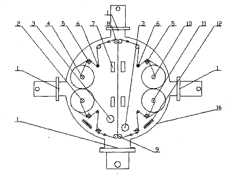
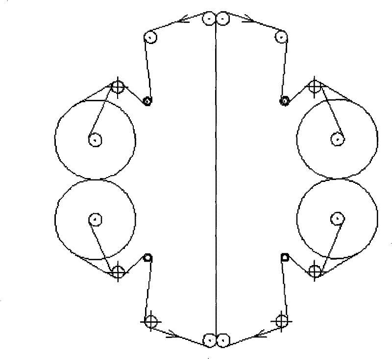
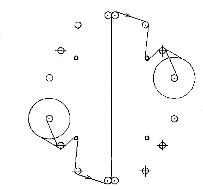
[0022] A vacuum magnetron sputtering winding coating device, such as figure 1 , Figure 7 and Figure 8 As shown, it includes a vacuum chamber 16, a vacuum obtaining system 1, a target 7, a target 7 and a winding system 15, the vacuum chamber 16 is provided with a vacuum obtaining system 1, and the vacuum obtaining system 1 makes the inside of the vacuum chamber 16 It is in a vacuum state during operation, and the magnetron sputtering area in the vacuum cavity 16 is provided with a magnetron sputtering target 7 . There are two rows of target poles 7 for magnetron sputtering, and the two rows of target poles 7 can be arranged in an opposite form, or in a staggered form. Rewinding and unwinding systems 15 are respectively arranged on both sides of the magnetron sputtering area. The ...


PUM


Abstract

A vacuum magnetron sputtering winding coating device, including a vacuum chamber, a vacuum acquisition system, a target and a winding system, the vacuum chamber is provided with a vacuum acquisition system, and the vacuum acquisition system makes the inside of the vacuum chamber work It is in a vacuum state, and the magnetron sputtering area in the vacuum chamber is provided with magnetron sputtering targets. The advantages of the present invention are: (1) The vacuum cavity is circular, no dead angle of pumping will be formed, and the vacuum degree is uniform; there is no oil return in the vacuum chamber; and the working efficiency is improved. (2) The double take-up and unwinding system is adopted, which can meet the full width of the magnetron sputtering area for one roll of double-sided plating and two rolls of single-sided plating; it can also meet the half-width of the plating area for two rolls of single-sided and double-sided plating ,Full-featured. (3) Perform ion bombardment on the surface of the substrate to increase the surface roughness of the substrate and ensure the peel strength between the film layer and the substrate.

Description

technical field [0001] The invention relates to the field of coating equipment for continuous film formation by magnetron sputtering on the surface of various substrates in a high vacuum state, specifically a vacuum that can be applied to sputtering one or more layers of metal on a roll-shaped substrate. Magnetron sputtering roll-to-roll coating device. Background technique [0002] Vacuum magnetron sputtering equipment can obtain one or more uniform deposition layers on conductive substrates and non-conductive substrates. It is an important equipment for obtaining various functional films and can be applied to EMI, flexible circuit boards, optical coatings, etc. industry. At present, the commonly used vacuum magnetron sputtering coating machine consists of a vacuum chamber, a vacuum acquisition system, a winding system, a sputtering target system and an automatic control system. The operation procedure is as follows: feeding - closing the vacuum chamber door - turning on ...

Claims


Application Information

Patent Timeline
Patent Type & Authority Patents(China)
IPC IPC(8): C23C14/35
Inventor 夏登峰苏陟郑永德杨伟民
Owner GUANGZHOU FANGBANG ELECTRONICS
Why Eureka
Try Eureka