
Nozzle system capable of continuously evening chemical vapour deposition of large area

A chemical vapor deposition, large-area technology, used in gaseous chemical plating, metal material coating processes, coatings, etc., which can solve nozzle blockage, film thickness, uneven optical and electrical properties of components, and change the composition of the reaction mixture gas. ingredients, etc.

Inactive Publication Date: 2009-07-29
CHUANGDA SOLAR ENERGY TECH OF ZHANGZHOU DEV ZONE INVESTMENT PROMOTION BUREAU
View PDF0 Cites 1 Cited by
  • Summary
  • Abstract
  • Description
  • Claims
  • Application Information

AI Technical Summary

Problems solved by technology

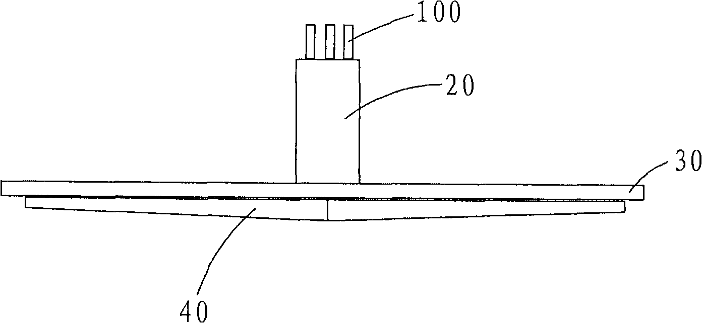
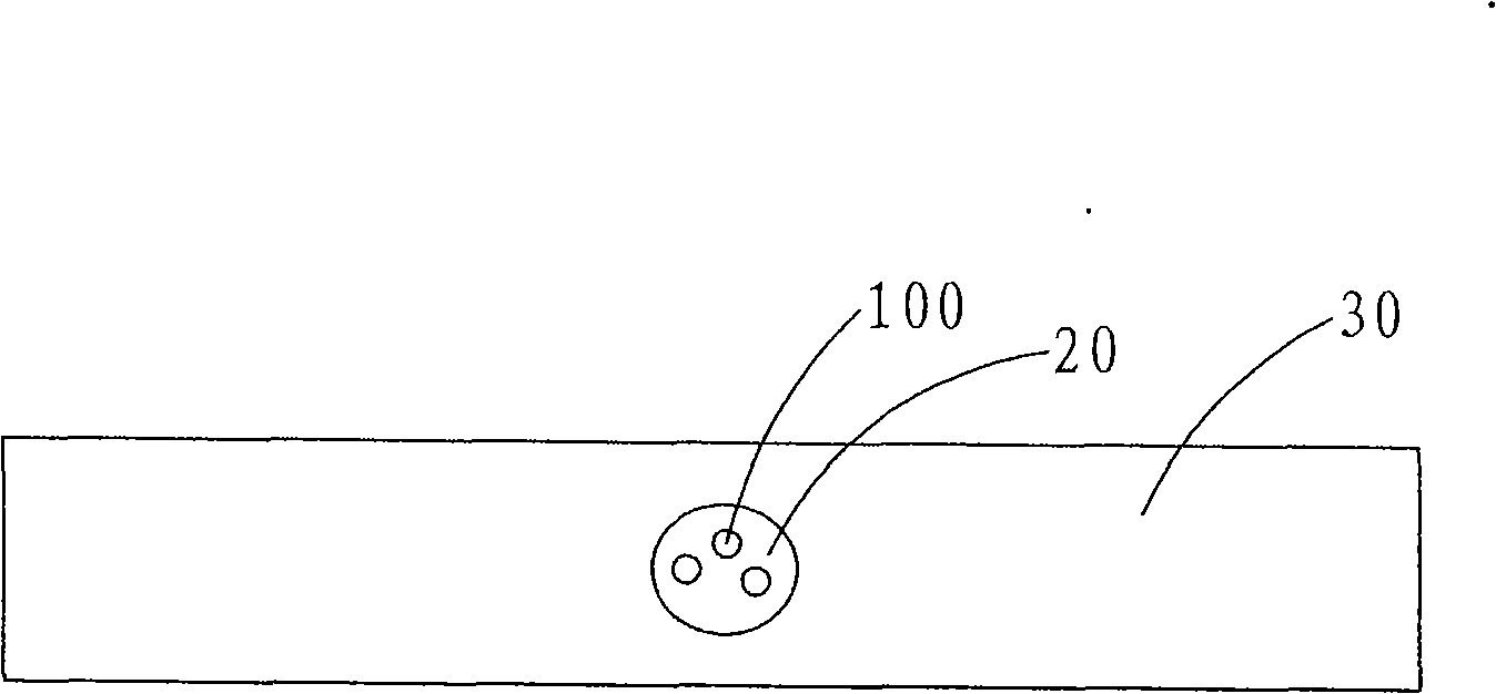
This structure makes the nozzle 40 from which the mixed reaction gas is ejected always be at a higher temperature. At the same time, too high temperature will cause the mixed gas to react in advance in the mixing chamber 20 or the nozzle 40, which will not only change the reaction The composition of the mixed gas will also correspondingly block the nozzles of the mixing chamber 20 and the nozzle 40 in the nozzle system, and finally cause the prepared film to show macroscopic differences in thickness, composition, and optical and electrical properties of the film. uniform

Method used


Image

  • Nozzle system capable of continuously evening chemical vapour deposition of large area
  • Nozzle system capable of continuously evening chemical vapour deposition of large area
  • Nozzle system capable of continuously evening chemical vapour deposition of large area

Examples


specific approach 1

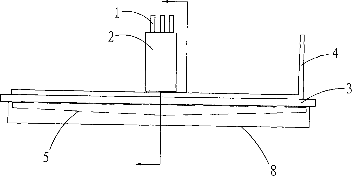
[0043] Concrete plan one: the V-shaped angle of the secondary reaction gas mixing chamber 8 is 20°, the volume ratio of the secondary reaction gas mixing chamber 8 and the volume of the nozzle 5 is 4:1, the secondary reaction gas mixing chamber The ratio of 8 to the volume of the primary reaction gas mixing chamber 2 is 1:1. Circulating water cooling system 4 The ratio of the cooling water pipe through which the cooling water circulates and the fixed panel 3 of the nozzle 5 to the area of ​​the fixed panel 3 of the entire nozzle 5 is 1 / 8; the cooling is regulated by a continuously adjustable flow controller The water velocity is 1.2 meters per second and the flow rate is controlled at 60 liters per minute. It is actually measured that the mixing temperature of the reaction gas in the primary reaction gas mixing chamber 2 on the upper part of the fixed panel 3 of the nozzle 5 is between 87°C and 119°C, and the mixed reaction gas measured by three uniformly distributed thermocou...

specific approach 2

[0044] Concrete plan two: the V-shaped angle of the secondary reaction gas mixing chamber 8 is 15°, the ratio of the volume of the secondary reaction gas mixing chamber 8 to the volume of the nozzle 5 is 4:1, the secondary reaction gas mixing chamber The ratio of 8 to the volume of the primary reaction gas mixing chamber 2 on the upper part of the fixed panel 3 of the nozzle 5 is 1:1. Circulating water cooling system 4 The ratio of the cooling water pipe through which the cooling water circulates and the fixed panel 3 of the nozzle 5 to the area of ​​the fixed panel 3 of the entire nozzle 5 is 1 / 11; the cooling water is adjusted by a continuously adjustable flow controller The flow rate is 1.5 meters per second and the flow rate is controlled at 50 liters per minute. It is actually measured that the mixing temperature of the reaction gas in the primary reaction gas mixing chamber 2 on the upper part of the fixed panel 3 of the nozzle 5 is between 94°C and 123°C, and the mixed ...

specific approach 3

[0045] Concrete scheme three: the angle of the V shape of the secondary reaction gas mixing chamber 8 is 20 °, the volume ratio of the volume of the secondary reaction gas mixing chamber 8 and the nozzle 5 is 4: 1, the secondary reaction gas mixing chamber The volume ratio of the body 8 and the primary reaction gas mixing chamber 2 on the upper part of the fixed panel 3 of the nozzle 5 is 1:1. Circulating water cooling system 4 The ratio of the cooling water pipe through which the cooling water circulates and the fixed panel 3 of the nozzle 5 to the area of ​​the fixed panel 3 of the entire nozzle 5 is 1 / 11; the cooling is regulated by a continuously adjustable flow controller The water velocity is 1.5 meters per second and the flow rate is controlled at 60 liters per minute. It is actually measured that the mixing temperature of the reaction gas in the primary reaction gas mixing cavity 2 on the upper part of the fixed panel 3 of the nozzle 5 is between 97°C and 126°C, and th...


PUM


Abstract

The invention discloses a spray head system capable of continuously homogenizing chemical vapor deposition in large area. The system comprises a conveying tube, a fixed panel, a primary reaction gas mixing cavity and a jet tube, wherein the primary reaction gas mixing cavity is arranged at the upper part of the fixed panel; the jet tube is arranged at the lower part of the fixed panel; the jet tube is provided with a jet exhaust; a circulating water cooling system is also arranged at the upper part of the fixed panel; a secondary reaction gas mixing cavity is also arranged at the lower part of the fixed panel; the jet tube is covered in the secondary reaction gas mixing cavity; the cross section of the secondary reaction gas mixing cavity is in a V shape; a monolete nozzle is arranged on the bottom of the secondary reaction gas mixing cavity; and raw material gas enters the primary reaction gas mixing cavity through the conveying tube, enters the jet tube, then enters the secondary reaction gas mixing cavity after the gas is sprayed from the jet exhaust of the jet tube, and finally is sprayed out from the monolete nozzle. The system can lower the deposition temperature so as to lead homogenization of a film to be easily controlled during large-area deposition, thereby ensuring normal running of continuous large-scale production.

Description

technical field [0001] The invention relates to a nozzle system capable of continuous large-area and uniform chemical vapor deposition, which continuously deposits a large-area and uniform transparent conductive film FTO (that is, fluorine-doped element di Tin oxide conductive film) is necessary for the nozzle system. Background technique [0002] As a new type of green energy, solar energy has advantages such as unlimited and no geographical application restrictions, and can be matched with conventional power grids. And it has become an important choice for countries all over the world as a sustainable new energy source. Solar cells directly convert the energy of the part of the sun irradiated on the earth into electrical energy, and it has almost no pollution and impact on the environment. Thin-film solar cells have good semiconductor optoelectronic properties and relatively low overall cost, and large-scale production can make them have an outstanding cost advantage in ...

Claims


Application Information

Patent Timeline
IPC IPC(8): C23C16/44C23C16/30
Inventor 郑玉祥周均范红兵陈飞赵国旭
Owner CHUANGDA SOLAR ENERGY TECH OF ZHANGZHOU DEV ZONE INVESTMENT PROMOTION BUREAU
Learn More