Solar photovoltaic power generation system, vehicle, solar photovoltaic power generation system control method, and computer readable recording medium having recorded therein program for causing compu
A technology of a power generation system and a control method, which is applied to the control of a photovoltaic power generation system, a vehicle, a photovoltaic power generation system, and a computer-readable storage medium storing a program for enabling a computer to execute the control, can solve the tracking delay , the reduction of power generation efficiency, and the relatively drastic changes in the amount of sunlight, to achieve the effect of reducing system costs and preventing the decline of power generation efficiency
- Summary
- Abstract
- Description
- Claims
- Application Information
AI Technical Summary
Problems solved by technology
Method used
Image
Examples
Embodiment approach 1
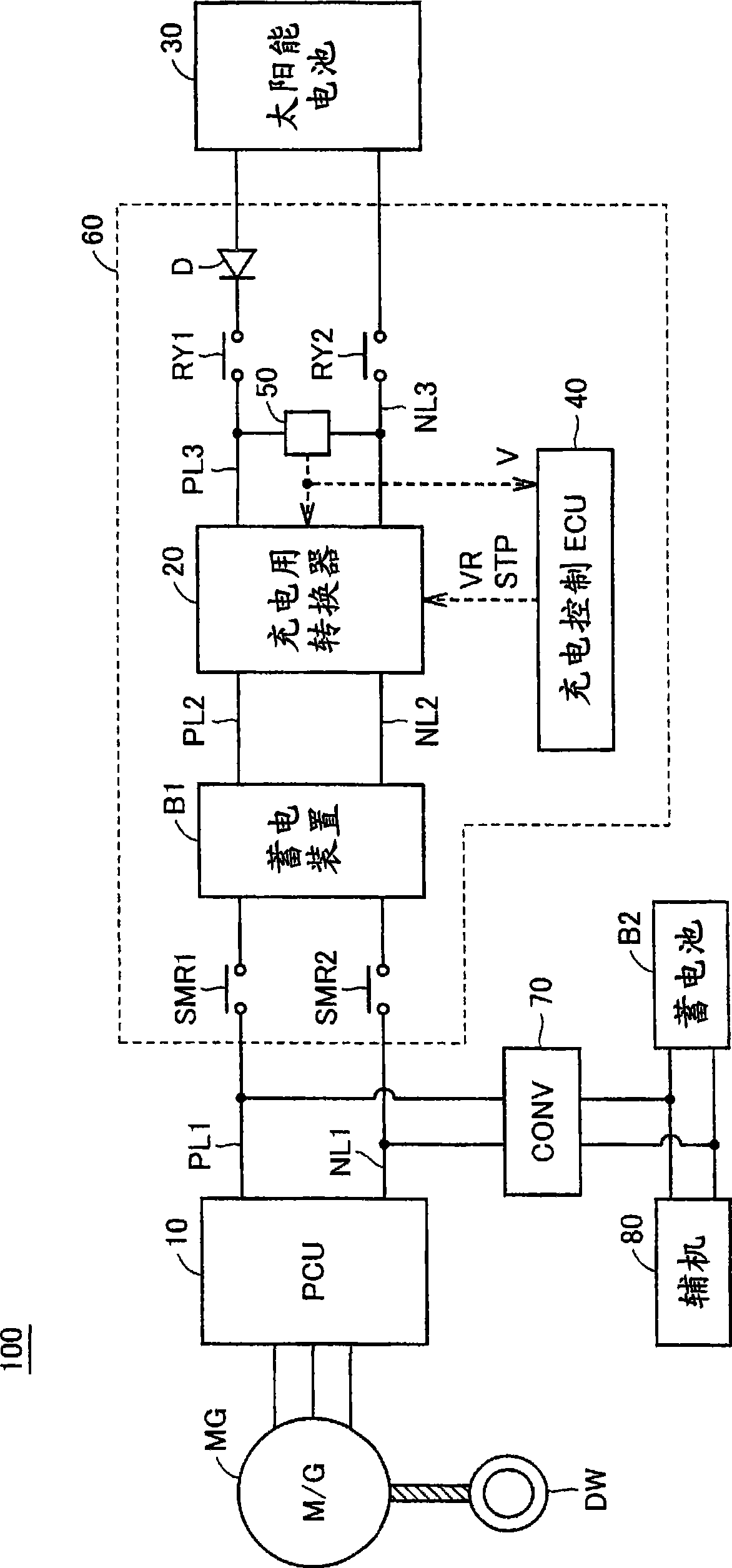
[0050] figure 1 It is an overall block diagram of the vehicle according to Embodiment 1 of the present invention. refer to figure 1 , the vehicle 100 includes a power storage device B1, system main relays SMR1, SMR2, a power control unit (Power Control Unit: hereinafter also referred to as “PCU”) 10, a motor generator MG, and drive wheels DW. In addition, vehicle 100 further includes a charging converter (converter) 20 , relays RY1 and RY2 , a diode D, a solar battery 30 , a charging control ECU (Electronic Control Unit) 40 , and a voltage sensor 50 . In addition, vehicle 100 further includes a DC-DC converter (converter) 70 , auxiliary battery B2 , and auxiliary equipment 80 .
[0051] System main relays SMR1 and SMR2 , power storage device B1 , charging converter 20 , voltage sensor 50 , relays RY1 and RY2 , diode D, and charging control ECU 40 are accommodated in a battery pack 60 . System main relay SMR1 is connected between the positive electrode of power storage dev...
Embodiment approach 2
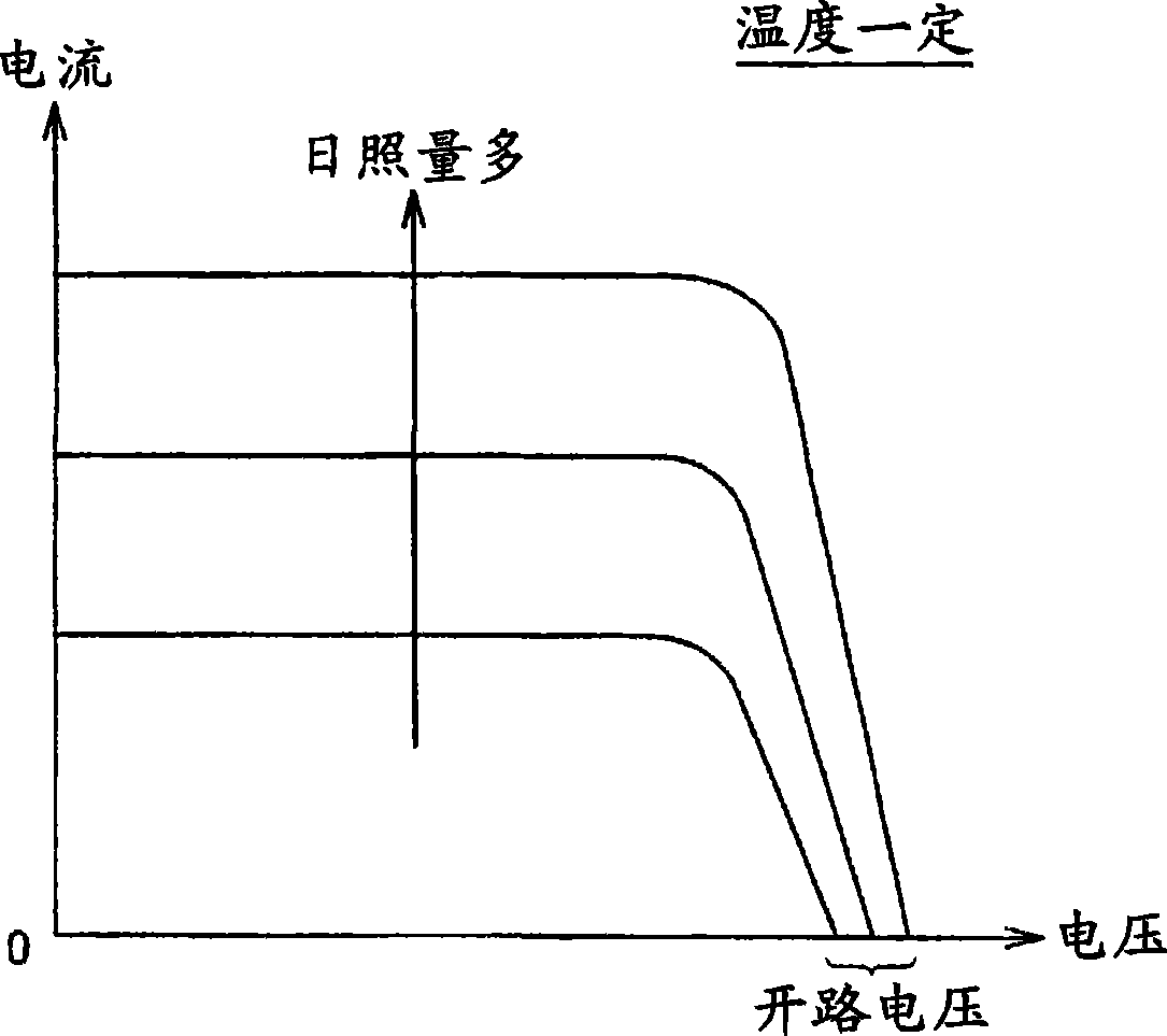
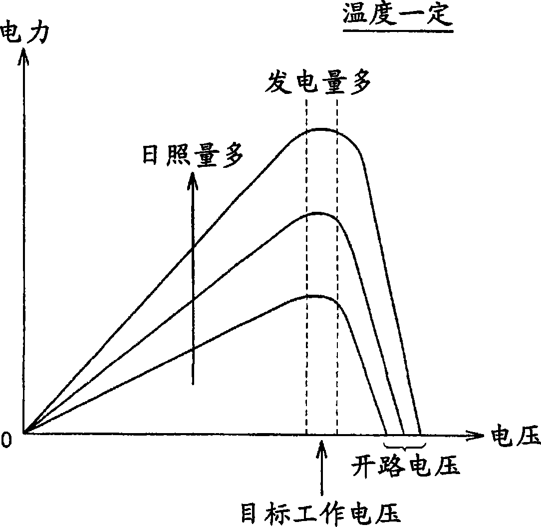
[0085] In Embodiment 1, the open circuit voltage of solar cell 30 is detected by temporarily stopping power generation of solar cell 30 , but in Embodiment 2, the temperature of solar cell 30 is detected, and the open circuit voltage is estimated based on the detected temperature.
[0086] Image 6 It is the overall block diagram of the vehicle of Embodiment 2. refer to Image 6 , vehicle 100A at figure 1 In the configuration of vehicle 100 according to Embodiment 1 shown, temperature sensor 90 is further provided, and charge control ECU 40A is provided instead of charge control ECU 40 .
[0087] Temperature sensor 90 detects temperature T of solar battery 30 and outputs the detected value to charging control ECU 40A. Charge control ECU 40A estimates the open-circuit voltage of solar cell 30 based on temperature T of solar cell 30 detected by temperature sensor 90 , and determines an operating voltage at which output power becomes maximum based on the estimated open-circuit...
Embodiment approach 3
[0104] In Embodiment 3, a measuring solar cell not connected to charging converter 20 is provided, and the operating voltage of solar cell 30 is determined based on the open circuit voltage of the measuring solar cell.
[0105] Figure 10 It is the overall block diagram of the vehicle of Embodiment 3. refer to Figure 10 , vehicle 100B at figure 1 The configuration of the vehicle 100 according to Embodiment 1 shown further includes a measurement solar cell 32 and a voltage sensor 52 , and includes a charge control ECU 40B instead of the charge control ECU 40 .
[0106] The measuring solar cell 32 is a single solar cell for measuring the open circuit voltage, and is not electrically connected to the solar cell 30 and the charging converter 20 . In addition, since the measuring solar cell 32 is not used for power generation, a small and inexpensive solar cell can be used. The voltage sensor 52 detects the open circuit voltage Vm of the solar cell 32 for measurement, and outp...
PUM
 Abstract
Description
Claims
Application Information
 - R&D
- Intellectual Property
- Life Sciences
- Materials
- Tech Scout
- Unparalleled Data Quality
- Higher Quality Content
- 60% Fewer Hallucinations
Browse by: Latest US Patents, China's latest patents, Technical Efficacy Thesaurus, Application Domain, Technology Topic, Popular Technical Reports.
© 2025 PatSnap. All rights reserved.Legal|Privacy policy|Modern Slavery Act Transparency Statement|Sitemap|About US| Contact US: help@patsnap.com


