Closed type hydraulic transmission for heliostat of solar thermal power generation system

A hydraulic transmission device, solar thermal power generation technology, applied in the direction of solar thermal power generation, mechanical power generated by solar energy, fluid pressure actuation device, etc., can solve the problems of poor control reliability, large installation space, low efficiency, etc., and achieve reliability Improvement, low manufacturing cost and high transmission efficiency

Inactive Publication Date: 2009-08-19
HARBIN INST OF TECH +1
View PDF0 Cites 10 Cited by
  • Summary
  • Abstract
  • Description
  • Claims
  • Application Information

AI Technical Summary

Problems solved by technology

[0005] In order to solve the problems of large installation space, low efficiency and poor control reliability in the existing hydraulic transmission device of the heliostat, the present invention further provides a closed hydraulic transmission device used on the heliostat of the solar thermal power generation system

Method used


Image

  • Closed type hydraulic transmission for heliostat of solar thermal power generation system

Examples


specific Embodiment approach 1

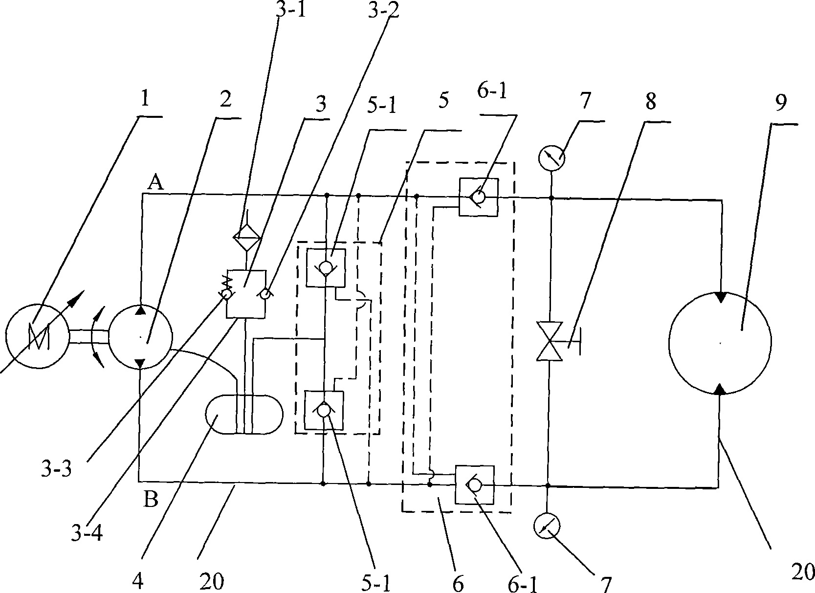
[0009] Specific implementation mode one: as figure 1 As shown, the closed hydraulic transmission device used on the heliostat of the solar thermal power generation system described in this embodiment includes an AC servo motor or a frequency conversion motor 1, a bidirectional quantitative pump 2, a pre-pressed air filter 3, a sealed Pressure oil tank 4, replenishment valve assembly 5, two-way hydraulic lock assembly 6 and swing hydraulic motor 9, the AC servo motor or frequency conversion motor 1 is connected to the two-way quantitative pump 2 through a coupling, and the two-way quantitative pump 2 is connected to the swing A closed circuit 20 is formed between the hydraulic motors 9, the oil discharge port of the two-way quantitative pump 2 communicates with the sealed pressure oil tank 4, the pre-pressurized air filter 3 communicates with the sealed pressure oil tank 4 through the oil pipe, and the oil supply valve assembly 5 is connected in parallel on the closed circuit 2...

specific Embodiment approach 2

[0010] Specific implementation mode two: as figure 1 As shown, the pre-pressurized air filter 3 in this embodiment is composed of an air filter 3-1, an intake check valve 3-2 and an exhaust check valve 3-3, and the intake check valve 3-2 and the exhaust one-way valve 3-3 are connected in parallel through the oil pipe to form the circuit 3-4, the air filter 3-1 is connected in series with one end of the circuit 3-4, and the other end of the circuit 3-4 is connected with the closed pressure oil tank 4 connected. A pre-pressurized air filter 3 is installed on the airtight pressure oil tank 4 to ensure that the airtight pressure oil tank has a certain positive pressure. Other components and connections are the same as those in the first embodiment.

specific Embodiment approach 3

[0011] Specific implementation mode three: as figure 1 As shown, the replenishment valve assembly 5 in this embodiment is composed of two plug-in hydraulic control check valves 5-1 butted together. The oil supply valve assembly 5 composed of two plug-in hydraulic control check valves 5-1 connected in series is connected in parallel in a closed circuit, which can reliably ensure that the oil suction port of the quantitative pump is connected to the (small) sealed pressure oil tank 4 The hydraulic oil is communicated to compensate the leakage of the two-way quantitative pump 2 and the swing hydraulic motor 9, to ensure that the pressure in the low-pressure pipeline (oil pipe) is greater than the air separation pressure, and to prevent cavitation and air infiltration. Other compositions and connections are the same as those in Embodiment 1 or 2.


PUM


Abstract

A closed hydraulic driving device of a heliostat for solar heat generating system relates to a hydraulic driving device. The invention solves the problems of big mounting space, low efficiency and bad control reliability existing in the existing hydraulic driving device of a heliostat. In the invention, an alternating-current servo motor or variable-frequency motor is connected with a bidirectional constant rate pump, the bidirectional constant rate pump and a rotary hydraulic motor constitute a closed loop, the drainage port of the bidirectional constant rate pump is communicated with a closed pressure oil tank, a precompressed air cleaner is communicated with the closed pressure oil tank, a slippage pump assembly is connected on the closed loop in parallel and is communicated with the closed pressure oil tank, and a bidirectional hydraulic lock assembly is serially connected on the closed loop. The device has the advantages of simple transmission and driving form, good reliability, high transmission efficiency, energy utilization, good energy saving effect, long service life, and low manufacturing and maintenance cost. The transmission device and driving device in modular integrated design are particularly applied to large-scale and massive heliostats.

Description

technical field [0001] The invention relates to a hydraulic transmission device used in a solar thermal power generation system, in particular to a closed hydraulic transmission device used on a heliostat of a tower type solar thermal power generation system. Background technique [0002] Tower-type solar thermal power generation system is also called concentrated solar thermal power generation system. Its basic form is to use a group of heliostats that independently track the sun to gather sunlight to the receiver fixed on the top of the tower to generate high temperature and heat the working fluid. Generate superheated steam or high-temperature gas to drive a steam turbine generator set or a gas turbine generator set to generate electricity, thereby converting solar energy into electrical energy. Studies have shown that solar thermal towers will be the cheapest of all solar power technologies when it comes to large-scale power generation. A heliostat is a concentrating de...

Claims


Application Information

Patent Timeline
Patent Type & Authority Applications(China)
IPC IPC(8): F03G6/06F15B15/18
CPCY02E10/46
Inventor 苏文海白洋姜继海刘汶峰刘涛张舒赵立军罗念宁刘庆和
Owner HARBIN INST OF TECH
Why Eureka
Try Eureka