

Laser differential confocal spectrum microscopy tomography device
A differential confocal and tomographic imaging technology, used in measurement devices, material excitation analysis, optics, etc., can solve the problem of poor geometric position detection ability, difficulty in accurately capturing excitation Raman spectra, and low response sensitivity of confocal microscope characteristic curves, etc. problem, to achieve the effect of improving detection ability and achieving absolute measurement
Inactive Publication Date: 2010-11-10
BEIJING INSTITUTE OF TECHNOLOGYGY
View PDF0 Cites 1 Cited by
- Summary
- Abstract
- Description
- Claims
- Application Information
AI Technical Summary
Problems solved by technology
Confocal microscopes are widely used in cutting-edge disciplines and fields such as biomedicine, materials science, and high-energy physics because of their spectral tomography capabilities, and because of their high resolution, they can perform fine imaging of living biological samples and tiny industrial products , providing the microscopic geometrical information and material spectral information of the sample, it has become a powerful tool for medical observation and manufacturing inspection; however, to improve the micro-region detection capability of the confocal Raman spectroscopy microscope system, it is necessary to accurately determine the sample focus, so that the sample is located near the focal point O, but the response sensitivity of the confocal microscope characteristic curve near the focal point O is extremely low. The ability to detect the "geometric position of the region" cannot be achieved at the same time, that is, the existing confocal Raman spectroscopic microscopy technology has the following principle defects:
1. The spectral detection ability at the focal point O is strong, but the geometric position detection ability is poor;
2. It is difficult to accurately capture the excited Raman spectrum at the focal point O to achieve micro-region spectral detection;
3. Restricted by the diffraction limit, the size of the spot at the focal point O and the depth of focus will restrict the axial and lateral resolution capabilities of the confocal Raman spectroscopy microscope system, etc.
However, there is no report on the spectral imaging technology that uses the combination of differential confocal technology and confocal Raman spectroscopy detection technology to simultaneously obtain the geometric shape and component information of the sample at the nanometer level.
Method used
View moreImage
Smart ImageViewing Examples

Examples
Embodiment Construction
Login to View More PUM
 Abstract
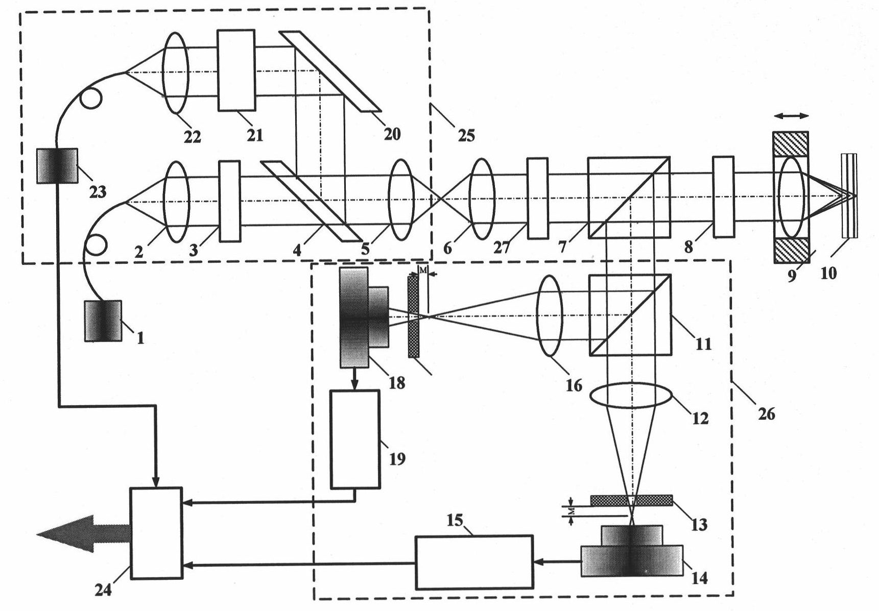
The invention belongs to the technical fields of optical microscopy imaging and optical precision measurement and relates to a laser differential confocal spectrum microscopy tomography device which mainly comprises a Raman spectrum analysis part (25) and an objective lens (6), a polarizing spectroscope (7), a one-quarter glass slide (8) and a measurement objective lens (9) which are sequentiallyarranged along the optical path; the laser differential confocal spectrum microscopy tomography device further comprises a differential confocal detection part (26) which is positioned in the reversedirection of the reflection direction of the polarizing beam splitter. The differential confocal detection part is used for measuring the geometric position of a micro-area of a sample and focusing the sample to obtain image information of the micro-area of the sample; the Raman spectrum analysis part is used for analyzing the material spectrum of the detected area of the sample to obtain component information of the micro-area of the sample; the combination of the two parts can realize the nano-level micro-area spectrum measurement of the sample and simultaneously obtain the geometric feature and the material component information of the micro-area of the sample. The laser differential confocal spectrum microscopy tomography device provides a powerful observation means for bio-medicine, material science, high-energy physics and other forefront subjects.
Description
Laser Differential Confocal Atlas Micro-tomography Device technical field The invention belongs to the technical field of optical microscopic imaging and spectral measurement, and relates to a laser differential confocal atlas microscopic tomography device, which can be used for high-precision three-dimensional shape measurement of samples and spectral analysis of material components in sample microregions. technical background In 1990, G.J.Puppels and other scholars first invented the confocal Raman spectroscopy microscopy technique when observing the morphology and composition of single cells and chromosomes, and successfully used it in experiments. The spectral imaging principle of the confocal Raman spectroscopy microscope is to place the point light source, the point object to be measured, and the spectral point detector at the corresponding conjugate position, which constitutes the layered structure of point illumination and point detection in optical imaging. Micros...
Claims
Login to View More Application Information
Patent Timeline
 Patent Type & AuthorityPatents(China)
IPC IPC(8): G01N21/65G01N21/64G01N13/00G02B27/09
Inventor赵维谦王允邱丽荣
OwnerBEIJING INSTITUTE OF TECHNOLOGYGY