
Laser

A laser and laser gain technology, applied in the laser field, can solve the problems of high cost, complex structure, waste of pumping light energy, etc., and achieve the effect of improving absorption efficiency

Inactive Publication Date: 2009-09-23
SHANGHAI BRANCH FUZHOU GAOYI COMM CO LTD
View PDF0 Cites 6 Cited by
  • Summary
  • Abstract
  • Description
  • Claims
  • Application Information

AI Technical Summary

Problems solved by technology

At present, the coupling methods such as lens group, optical fiber coupling, lens light guide and self-focusing micro-lens are mainly used, but the coupling method will bring the loss of pump light, limit the energy conversion efficiency of the laser, and especially have the disadvantages of complex structure and high cost.
And the commonly used LD pumping method, the pump light can only pass through the gain medium once or twice, for the gain medium with low absorption coefficient, or when the pump wavelength is not in the absorption center band of the gain medium, most of the pump light energy is wasted

Method used


Image

  • Laser
  • Laser
  • Laser

Examples


Embodiment Construction

[0039] The present invention will be further described in conjunction with the accompanying drawings and specific embodiments.

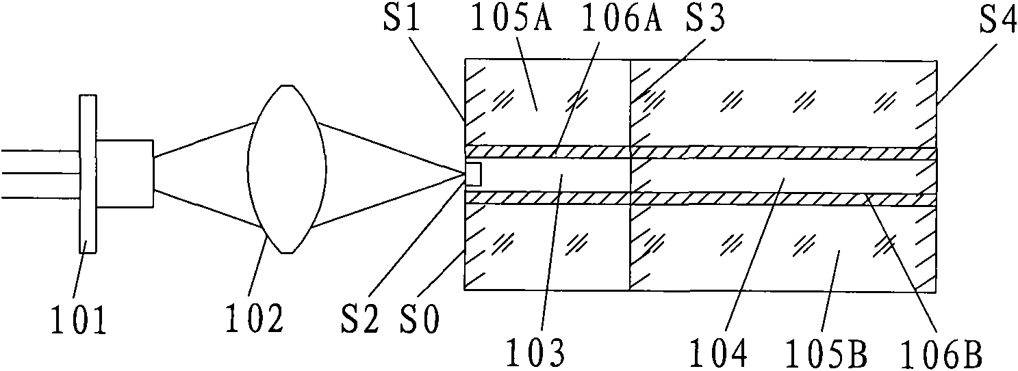
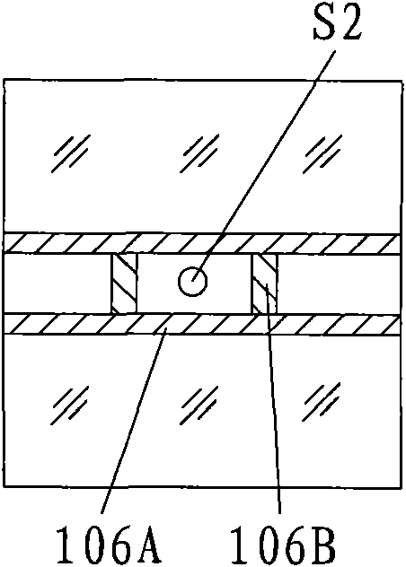
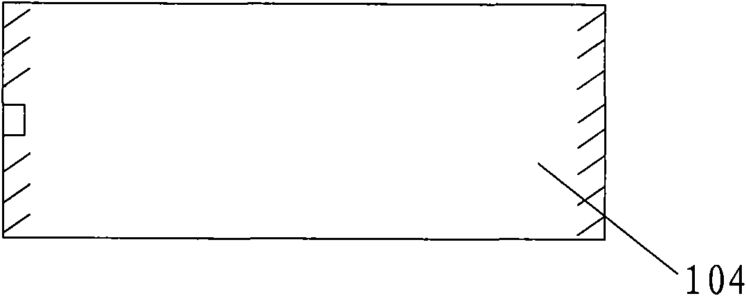
[0040] The invention adopts a new pumping cavity structure to improve the absorption efficiency of the laser gain medium to the pumping light. The structure includes LD pumping system, optical coupling system and resonant cavity. The gain medium in the resonant cavity can be rod-shaped, square-shaped, waveguide cavity, etc. On the pump light incident end face, except for the pump light through hole, the other surfaces that cannot produce total internal reflection are all coated with high-reflective pump light. The film layer is used to form a reflective cavity close to the closed structure of the pump light. After the LD pump light enters the gain medium, it will be reflected multiple times in the cavity of the pump light, most of which will be absorbed by the gain medium, and only a small amount will be lost through the aperture. Therefore, the pr...


PUM


Abstract

The invention relates to the laser field, in particular to the laser structure. The laser comprises a pump cavity, a pump light source, an optical coupling system and other optical elements, wherein the pump cavity is provided with a light-admitting hole at the pump point, the other part of the pump cavity is all coated with a reflective coating, and the position of the pump light source corresponds to the light-admitting hole. An enclosed cavity which has high reflectivity to the pump light is formed by the pump cavity except the light-admitting hole, therefore, the pump light is reflected by a plurality of times in the enclosed cavity, and most of the pump light is absorbed by a laser gain medium except that a little bit of the pump light escapes from the light-admitting hole of the pump light. The structure of the invention is beneficial to improving the absorption efficiency of the gain medium on the pump light; can be applied to manufacture lasers with wide temperature operation range for reducing or eliminating the influence on the laser power due to the semiconductor laser wavelength shift caused by temperature change; and can reduce the volume of the laser gain medium and simultaneously reduce the laser threshold as the length of the laser gain medium can be shorter.

Description

technical field [0001] The invention relates to the field of lasers, in particular to laser structures. Background technique [0002] LD-pumped solid-state lasers are widely used due to their advantages of high efficiency, good beam quality, long life, compact structure, and high repetition rate. However, the light emitted by LD has a large divergence angle. When using LD or LD array for end-face or side pumping, it needs to be collimated and converged efficiently. At present, the coupling methods such as lens group, fiber coupling, lens light guide and self-focusing microlens are mainly used, but the coupling method will cause the loss of pump light, limit the energy conversion efficiency of the laser, and especially have the disadvantages of complex structure and high cost. And the commonly used LD pumping method, the pump light can only pass through the gain medium once or twice, for the gain medium with low absorption coefficient, or when the pump wavelength is not in t...

Claims


Application Information

Patent Timeline
IPC IPC(8): H01S3/0941H01S3/091G02B1/10
Inventor 吴砺凌吉武陈燕平卢秀爱
Owner SHANGHAI BRANCH FUZHOU GAOYI COMM CO LTD
Learn More