Photoelectric-effect ion source based on carbon nano-tubes

A carbon nanotube and photoelectric effect technology, applied in the field of ion source, can solve the problems of inconvenient practical application, low conversion efficiency of ionization source, etc., and achieve the effects of good chemical stability, improved electron tunneling probability, and easy ionization process.

Active Publication Date: 2013-09-18
SUZHOU WEIMU INTELLIGENT SYST CO LTD
View PDF7 Cites 10 Cited by
  • Summary
  • Abstract
  • Description
  • Claims
  • Application Information

AI Technical Summary

Problems solved by technology

[0007] The technical problem to be solved by the present invention is that the conversion efficiency of the ionization source of metal photoelectric emission in the prior art is low, and the ionization source of carbon nanotubes used must keep the ionization chamber in a vacuum state, which is very inconvenient for practical applications, thereby providing a An ion source based on the photoelectric effect of carbon nanotubes with a wider range of applications and better effects

Method used


Image

  • Photoelectric-effect ion source based on carbon nano-tubes
  • Photoelectric-effect ion source based on carbon nano-tubes
  • Photoelectric-effect ion source based on carbon nano-tubes

Examples


Embodiment 1

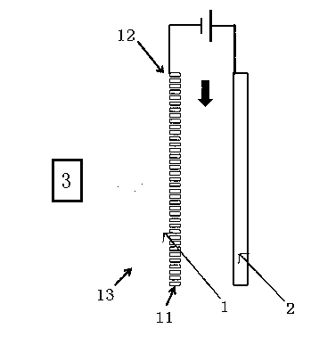
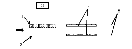
[0031] The structure of the ion source based on the photoelectric effect of carbon nanotubes according to the present invention is as figure 1 As shown, it includes a power supply, and the positive pole of the power supply is connected to the counter electrode 2; the counter electrode 2 preferably adopts a grid-like electrode. The negative pole of the power supply is connected with a carbon nanotube electrode 1, the carbon nanotube electrode 1 includes a carbon nanotube layer 11 and a substrate 12, and the carbon nanotube layer 11 in the carbon nanotube electrode 1 is single-walled carbon nanotube. The carbon nanotube layer 11 is arranged on the inner side of the substrate 12 and it is opposite to the counter electrode 2. The carbon nanotube layer in this embodiment is 300 nanometers, and between the carbon nanotube layer 11 and the counter electrode 2 There is a channel for the sample to pass through in the middle. The ultraviolet emitting device 3 irradiates the carbon nan...

Embodiment 2

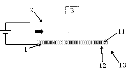
[0035] Another embodiment of the ion source based on the photoelectric effect of carbon nanotubes according to the present invention is figure 2 As shown, in this embodiment, the ultraviolet emitting device 3 is arranged behind the carbon nanotube electrode 1, and the ultraviolet rays can be irradiated on the substrate 12 by backlighting, since the substrate 12 is made of a transparent material such as Quartz glass sheet is used to ensure that effective ultraviolet rays can pass through smoothly. The ultraviolet rays pass through the substrate 12 to irradiate the carbon nanotube layer 11, and the thickness of the carbon nanotube layer 11 is 10-200 nanometers so that the ultraviolet rays can pass through.

Embodiment 3

[0037] The ion source based on the photoelectric effect of carbon nanotubes of the present invention, on the basis of the above embodiment 1, is provided with a temperature-controllable heating device 13 on the outside of the substrate 12, and the temperature-controllable heating device 13 Preferably, a temperature-controllable heating plate is used; the temperature-controllable heating device 13 heats the carbon nanotubes when they undergo the photoelectric effect, so as to help electrons overcome the potential barrier of work function and further improve the quantum coefficient of photoemission.


PUM


Abstract

The invention relates to a photoelectric-effect ion source based on carbon nano-tubes. The ion source comprises an ultraviolet ray emitting device and a power source, wherein the anode of the power source is connected with a counter electrode; the cathode of the power source is connected with a carbon nano-tube electrode, the carbon nano-tube electrode comprises a carbon nano-tube layer and a substrate, the carbon nano-tube layer is opposite to the counter electrode, and a passage which is used for a sample to pass through is reserved between the carbon nano-tube layer and the counter electrode; and the ultraviolet ray emitting device irradiates the carbon nano-tube electrode. According to the ion source, ions are generated through the photoelectric effect on the carbon nano-tubes, the carbon nano-tubes are very low in light reflection coefficient and very high in light absorption efficiency, the electron emission is easier due to the unique one-dimensional structure of the carbon nano-tubes, and the carbon nano-tubes can be used in an atmospheric state, so that the problem in the prior art that the vacuum is required when the field-effect ion emission is carried out by using the carbon nano-tubes is solved, the range of use is expanded, and the use is more convenient.

Description

technical field [0001] The invention relates to an ion source, in particular to an ion source based on the photoelectric effect of carbon nanotubes. Background technique [0002] The ion source is a device that ionizes neutral atoms or molecules and extracts an ion beam from it. It is a key device used in various analytical instruments such as mass spectrometers. Gas discharge, collision of electron beam to gas atoms or molecules, charged particle beam sputtering of working material and surface ionization process can all generate ions and be extracted into beams. According to different conditions of use and purposes, various types of ion sources have been developed. [0003] The ionization source commonly used in traditional ion mobility spectrometry is radioactive 63 Ni ionization source, but the safety inspection and special safety measures brought by the radioactive source have brought a lot of trouble to its practical application, no matter in production and user use, ...

Claims


Application Information

Patent Timeline
Patent Type & Authority Applications(China)
IPC IPC(8): H01J49/16
Inventor 李灵锋王向阳汪小知李鹏
Owner SUZHOU WEIMU INTELLIGENT SYST CO LTD
Why Eureka
Try Eureka