Liquid crystal panel and liquid crystal display device

A liquid crystal panel and liquid crystal cell technology, applied in optics, instruments, nonlinear optics, etc., can solve the problems of decreased contrast, increased thickness, and image chromatic aberration, and achieves high contrast, less light leakage, and small color shift effects.

Inactive Publication Date: 2009-09-23
NITTO DENKO CORP
View PDF8 Cites 5 Cited by
  • Summary
  • Abstract
  • Description
  • Claims
  • Application Information

AI Technical Summary

Problems solved by technology

However, conventional liquid crystal display devices equipped with liquid crystal cells of the IPS method have the following problems of deterioration of display characteristics: the contrast decreases in the oblique direction, and the chromatic aberration of the image (also referred to as the chromatic aberration in the oblique direction) that changes with the viewing angle changes occurs. color shift) etc.
Therefore, the thickness of the produced λ / 2 plate becomes large, which makes it difficult to reduce the thickness of the liquid crystal display device.

Method used

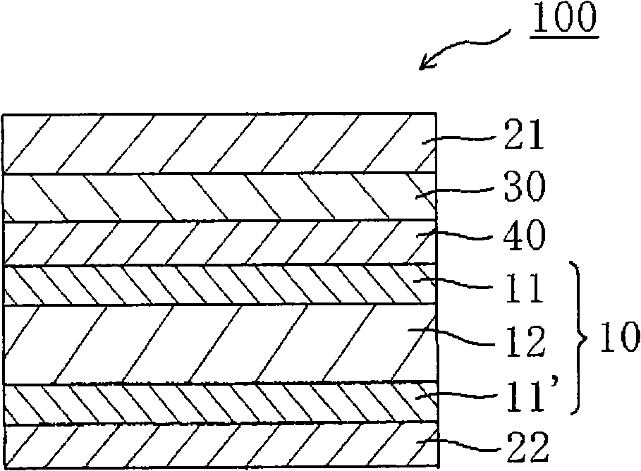
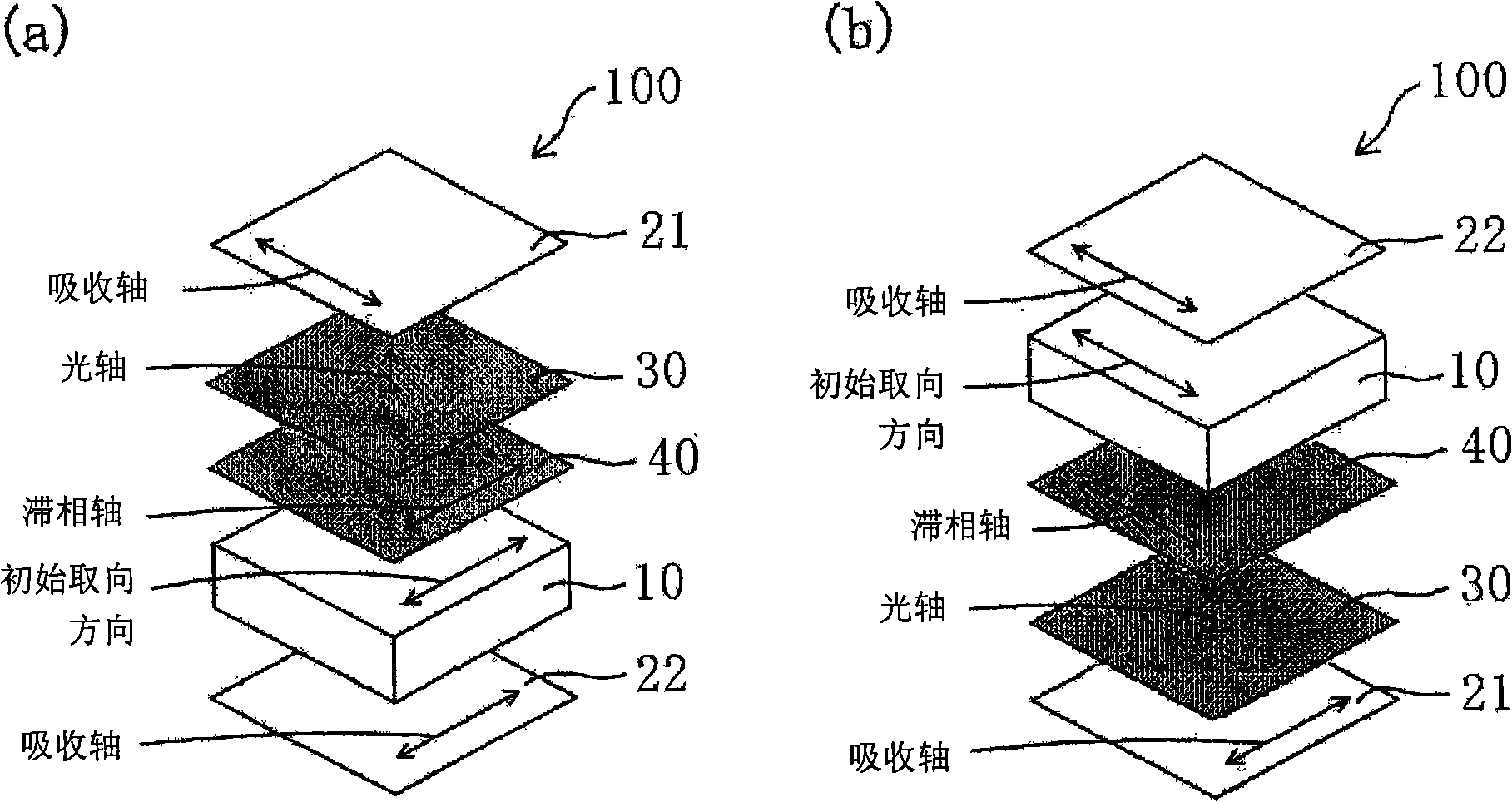
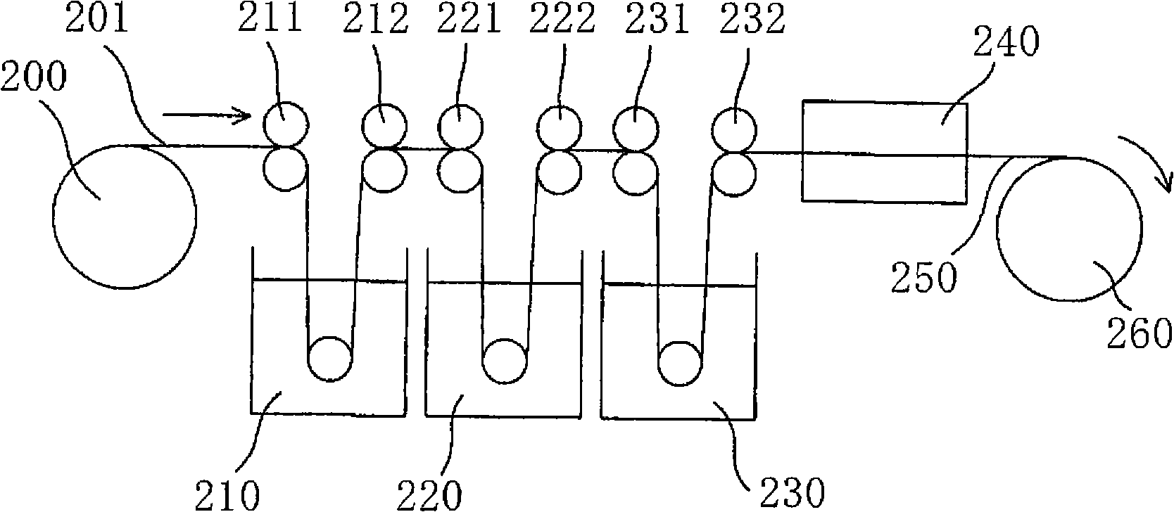

Image

  • Liquid crystal panel and liquid crystal display device
  • Liquid crystal panel and liquid crystal display device
  • Liquid crystal panel and liquid crystal display device

Examples


Embodiment

[0235] The present invention will be described more specifically using the following examples and comparative examples. Furthermore, the present invention is not limited to these examples. In addition, each analysis method used in the Example is as follows.

[0236] (1) Measuring method of monomer transmittance and degree of polarization of polarizer:

[0237] Measurement was performed at 23° C. using a spectrophotometer [manufactured by Murakami Color Technology Laboratory Co., Ltd. product name “DOT-3”].

[0238] (2) Determination method of thickness:

[0239] When the thickness is less than 10 μm, measurement is performed using a film spectrophotometer [product name "instant multichannel photodetector (internsified multichannel photodetector) MCPD-2000" manufactured by Otsuka Electronics Co., Ltd.). When the thickness is 10 μm or more, it measures using a digital micrometer “KC-351C type” manufactured by Anritsu Corporation.

[0240] (3) Determination method of phase di...

reference example 1

[0250] [Reference Example 1]: Production of Polarizer

[0251] A polymer film mainly composed of polyvinyl alcohol [Kuraray Co., Ltd. product name "9P75R (thickness: 75 μm, average degree of polymerization: 2,400, degree of saponification: 99.9 mol%)"] was kept at 30°C ± 3°C In a dyeing bath in which iodine and potassium iodide were mixed, the dyed side was uniaxially stretched to 2.5 times using a roll stretching machine. Next, in an aqueous solution of boric acid mixed with potassium iodide kept at 60±3°C, the crosslinking reaction is carried out while the uniaxial stretching is carried out, so that the polyvinyl alcohol film is stretched to 6 times the original length. The obtained film was dried in an air-circulating constant temperature oven at 50°C±1°C for 30 minutes to obtain polarizers P1 and P2 with a moisture content of 26%, a thickness of 28 μm, a degree of polarization of 99.9%, and a single transmittance of 43.5%.

reference example 2

[0252] [Reference Example 2]: Production of Polarizer Protective Film

[0253] A cellulose triacetate film (trade name "FUJITACUZ (thickness: 80 μm)" manufactured by Fuji Film Co., Ltd.) was used as a polarizer protective film.


PUM

PropertyMeasurementUnit
thicknessaaaaaaaaaa
thicknessaaaaaaaaaa
electrical conductivityaaaaaaaaaa

Abstract

Provided is very thin liquid crystal panel and liquid crystal display apparatus with a high contrast ratio in an oblique direction, less light leakage, and a small color shift in an oblique direction. The liquid crystal panel of the present invention includes a liquid crystal cell, a first polarizer arranged on one side of the liquid crystal cell, a second polarizer arranged on the other side of the liquid crystal cell, a first optical element arranged between the first polarizer and the liquid crystal cell, and a second optical element arranged between the first optical element and the liquid crystal cell. The first optical element has substantially optically negative uniaxial property, and the second optical element exhibits a refractive index ellipsoid of nx > nz > ny, and is formed of one or more kinds of polycylic compound having a -SO3 M group and / or a -COOM group (M represents a counter ion).

Description

technical field [0001] The invention relates to a liquid crystal panel with a liquid crystal unit, a polarizer and an optical element. In addition, the present invention relates to a liquid crystal display device using the above liquid crystal panel. Background technique [0002] Liquid crystal display devices have attracted attention due to their thinness, light weight, and low power consumption, and are widely used in mobile devices such as mobile phones and clocks; office automation equipment such as computer monitors and notebook computers; video cameras or LCD TV and other household electrical products, etc. The reason is that the display characteristics change with the viewing angle of the screen, or the shortcomings of being unable to operate under high temperature or extremely low temperature conditions have been continuously overcome through technological innovation. However, with the diversification of uses, it is gradually required to satisfy different character...

Claims


Application Information

Patent Timeline
Patent Type & Authority Applications(China)
IPC IPC(8): G02F1/13363G02B5/30
CPCG02F2413/02G02B27/281G02F1/133634G02F2413/07G02F2001/133635G02B5/3083G02F2413/12C09K2323/031G02F1/133635G02F1/1335G02B5/30G02F1/13363
Inventor 宫崎顺三松田祥一长塚辰树
Owner NITTO DENKO CORP
Why Eureka
Try Eureka