Eureka AIR delivers breakthrough ideas for toughest innovation challenges, trusted by R&D personnel around the world.

Bidimensional small angle measuring device based on shape of interference fringe

An angle measurement device and technology of a measurement device, applied in the field of precision measurement, can solve problems such as large volume, required load engraving, complex structure, etc., and achieve the effect of strong anti-interference ability, less optical components, and simple structure

Inactive Publication Date: 2009-09-30
HUBEI UNIV OF TECH
View PDF0 Cites 3 Cited by
  • Summary
  • Abstract
  • Description
  • Claims
  • Application Information

AI Technical Summary

Problems solved by technology

The photoelectric self-collimation method uses the directivity of the laser itself, takes the center of the laser light intensity distribution as the reference line, and uses the photodetector to detect the position of the spot to realize the measurement of the angle. This method is simple in structure and easy to use; During the measurement, due to the influence of the beam angle drift of the light source, the measurement results have low repeatability and poor stability, making it difficult to achieve high-precision measurement
[0004] Laser interferometry converts the direct measurement of the micro-angle of rotation of the object into the optical path difference between the measured object light and the reference light. Although this method has high precision, since the laser interferometer uses interference fringes for measurement, it has extremely high environmental requirements. Many external factors, such as surrounding air flow, vehicle operation, etc. will have a great impact on the measurement results, and the structure is complex and the volume is large.

Method used


Image

  • Bidimensional small angle measuring device based on shape of interference fringe
  • Bidimensional small angle measuring device based on shape of interference fringe

Examples


Embodiment Construction

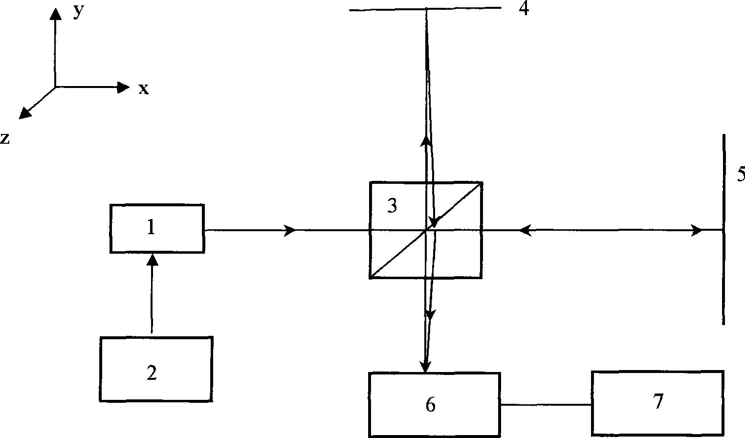
[0010] The structure and measurement principle of the optical system of the present invention will be described in further detail below in conjunction with the accompanying drawings.

[0011] Such as figure 1 As shown, a semiconductor laser is used in this embodiment, and the laser 1 may also be another type of laser, such as a He-Ne laser. The laser modulator 2 is used to modulate the laser. The modulation signal can be a triangular wave, a sawtooth wave or a sine wave. In this way, the wavelength and intensity of the beam emitted from the laser periodically change with the modulation signal. The beam is split by the beam splitter 3. There are two beams, one beam is incident on the reference mirror 5, the reflected light passes through the beam splitter 3, the other beam is incident on the mirror 4 fixed on the surface of the object to be measured, and the beam reflected from the mirror 4 is then split After the mirror 3 and the light reflected from the mirror 5, interference fr...


PUM


Abstract

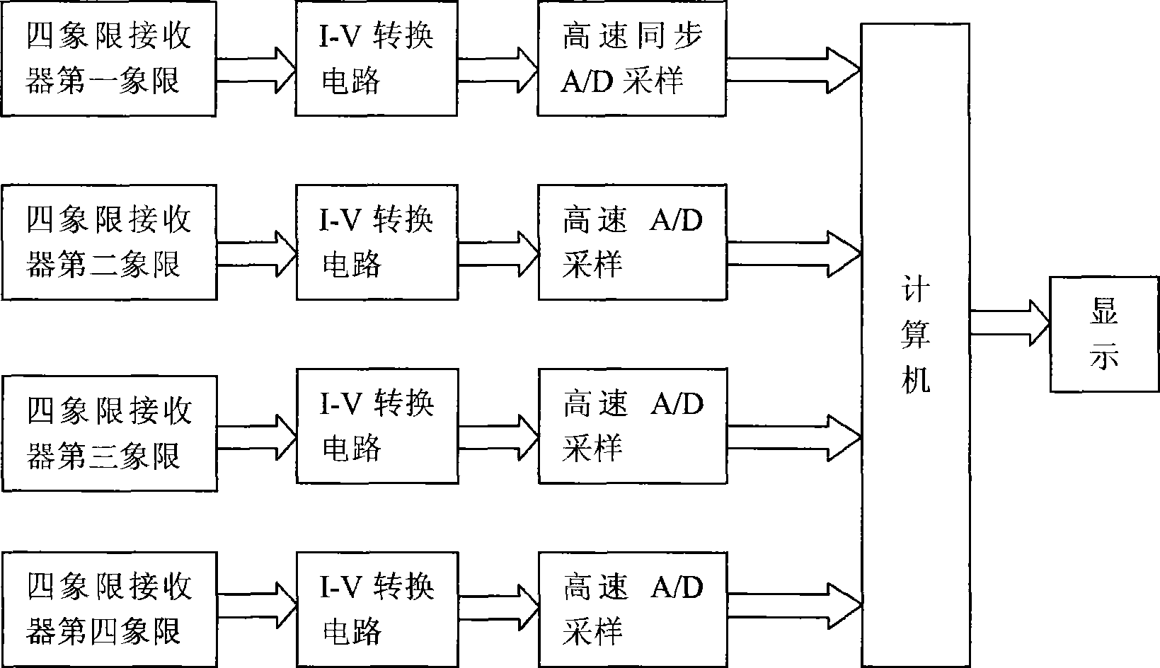
The invention discloses a bidimensional small angle measuring device based on the shape of an interference fringe and belongs to the technical field of precise measurement. The device comprises a laser, a spectroscope, a target reflector, a reference reflector and a four-quadrant receiver; and the target reflector is fixed on a measured object. A laser modulator modulates a light beam transmitted by the laser; the modulated light beam transmits the spectroscope and is divided into two beams; two beams are reflected by the target reflector and the reference reflector respectively, are returned to the spectroscope and are converged to generate the dynamic reference fringe; when the measured object has the angle change around z-axis, the width of the dynamic reference fringe is changed; and when the measured object has the angle change around x-axis, the width and the direction of the dynamic reference fringe are changed simultaneously. The dynamic reference fringe is received by the four-quadrant photoelectric receiver and converted into an electrical signal; the signal is subjected to current-voltage conversion and collected to a computer; and through the analysis of the variable quantity of the width and the direction of the fringe, the variable quantity of the angle of the measured object around the x-axis and z-axis is calculated. The bidimensional small angle measuring device has the advantages that the device adopts a wavelength modulation method and has good repeatability, good antijamming capacity, simple structure, small size and high precision which can reach 0.03 arcsec.

Description

Technical field [0001] The invention relates to a high-precision two-dimensional small-angle measurement device, which belongs to the technical field of precision measurement. Background technique [0002] The measurement of tiny angles has extremely important meaning and function in many fields such as precision machining, aerospace, military and communications. Optical goniometry has become an important method in the field of precision measurement technology due to its non-contact, high accuracy and high sensitivity. [0003] At present, optical small-angle measurement methods mainly include photoelectric autocollimator method and laser interferometry. The photoelectric self-collimation method uses the directivity of the laser itself, takes the laser light intensity distribution center as the reference line, and uses a photodetector to detect the position of the spot to achieve angle measurement. The method has a simple structure and is convenient to use; In the measurement, du...

Claims


Application Information

Patent Timeline
IPC IPC(8): G01B11/26
Inventor 翟中生王选择钟毓宁曹洪端杨练根
Owner HUBEI UNIV OF TECH
Why Eureka
Eureka Blog
Learn More