
A switch voltage regulation circuit and method with a frequency limiting function

A technology of switching voltage stabilization and switching voltage, which is applied in the direction of output power conversion devices, electrical components, and adjustment of electrical variables. It can solve problems such as radio wave and TV signal interference, large switching loss, and electromagnetic interference, and improve EMI distribution. , Reduce switching loss and improve efficiency

Active Publication Date: 2009-10-07
CHENGDU MONOLITHIC POWER SYST
View PDF4 Cites 58 Cited by
  • Summary
  • Abstract
  • Description
  • Claims
  • Application Information

AI Technical Summary

Problems solved by technology

Switching at high frequency in the switching power supply will cause serious electromagnetic interference (EMI), which not only reduces the quality of the power grid, but also affects the normal operation of electronic equipment connected to or near the switching power supply, and even affects radio waves and televisions. signal interference
For this reason, countries have established strict standards for EMI generated by switching power supplies. These EMI standards, such as EN55022, usually have lower limit values ​​in the high frequency band and higher limit values ​​in the low frequency band, so too high switching frequency will cause Switching power supply is difficult to pass EMI test
In addition, the higher the switching frequency, the greater the switching loss, which is not conducive to the improvement of the efficiency of switching power supply

Method used


Image

  • A switch voltage regulation circuit and method with a frequency limiting function
  • A switch voltage regulation circuit and method with a frequency limiting function
  • A switch voltage regulation circuit and method with a frequency limiting function

Examples


Embodiment Construction

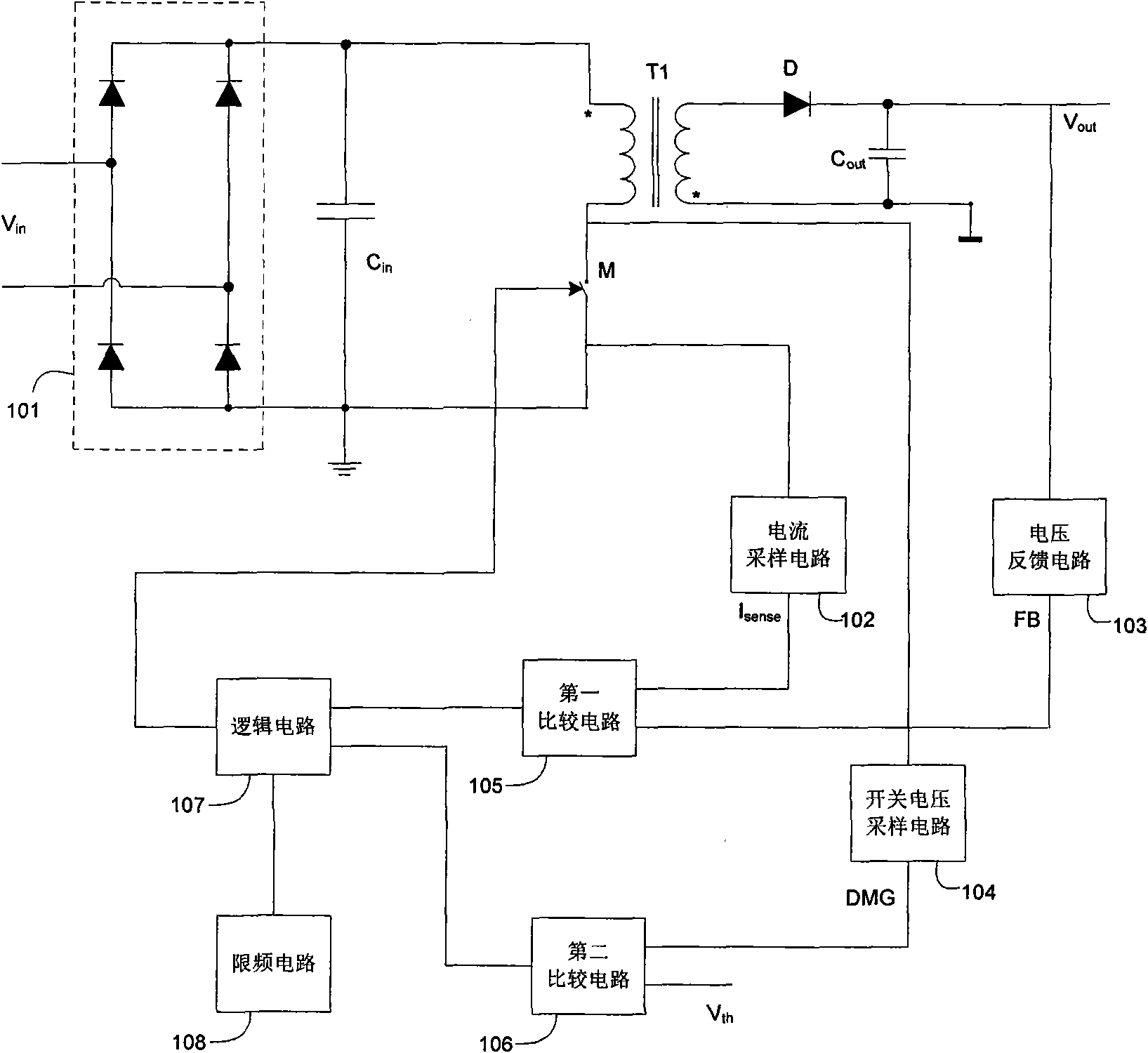
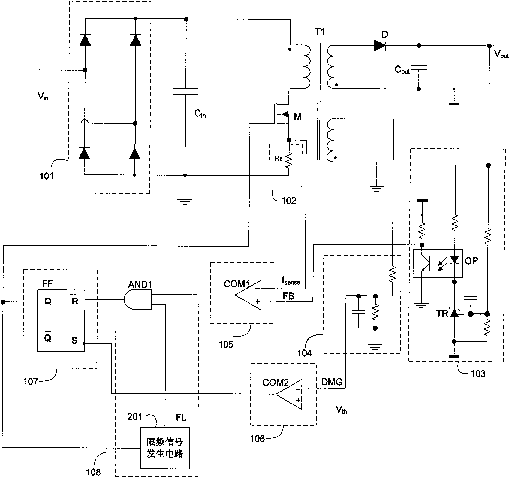
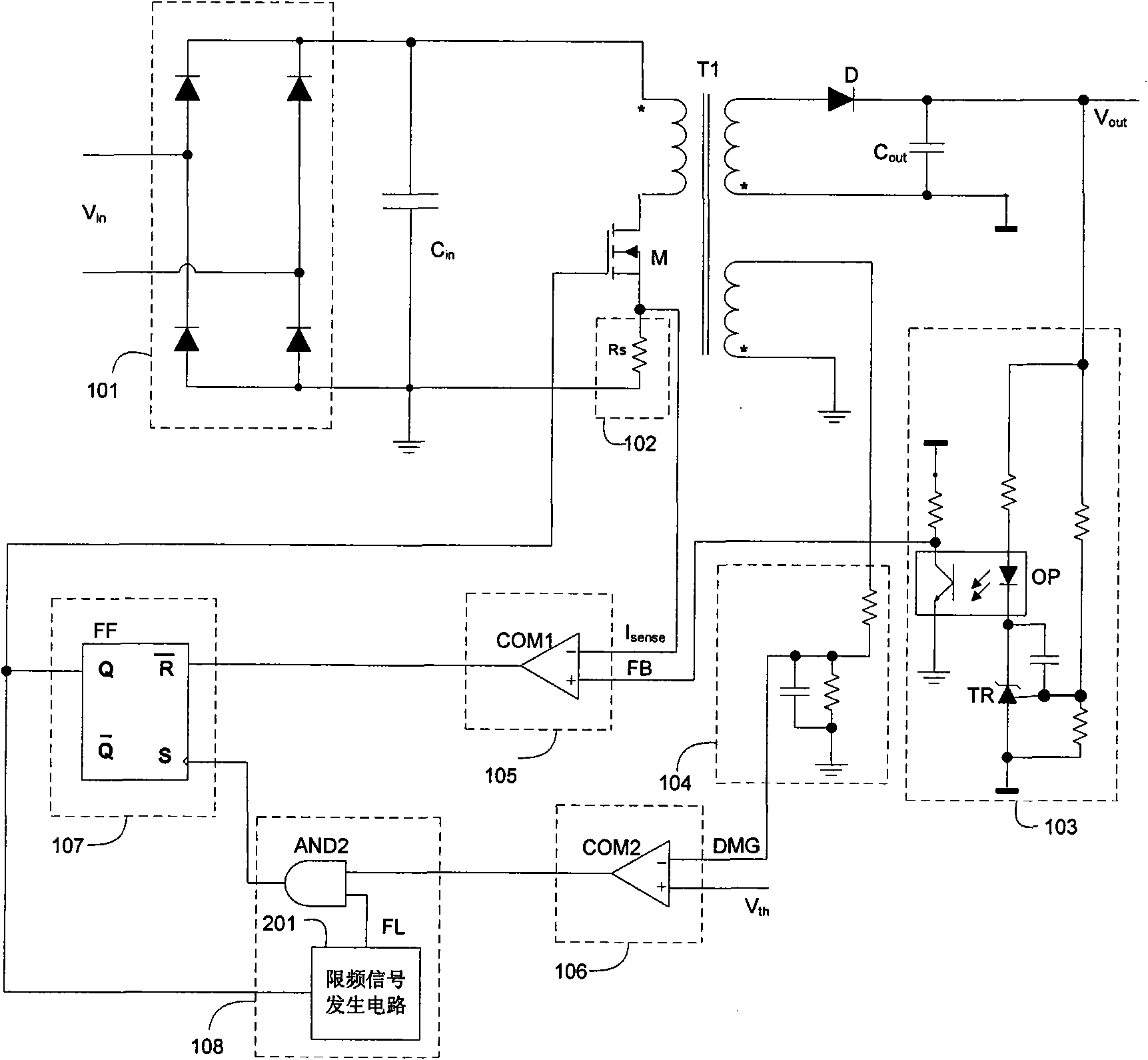
[0020] Specific embodiments of the present invention will be described in detail below, and it should be noted that the embodiments described here are only for illustration, not for limiting the present invention. The following all take the AC / DC (alternating current / direct current conversion) circuit comprising the flyback converter as an example to illustrate the present invention, but those skilled in the art know that the present invention can also be used in any DC / DC (direct current / direct current conversion) topology , Such as BUCK (buck) circuit, BOOST (boost) circuit, BUCK-BOOST (boost-buck) circuit, FLYBACK (flyback) circuit and FORWARD (forward) circuit, etc.

[0021] figure 1 It is a circuit diagram of a switching regulator circuit according to an embodiment of the present invention, including a rectifier bridge 101, an input capacitor C in , transformer T1, switch M, diode D, output capacitor C out , a current sampling circuit 102 , a voltage feedback circuit 10...


PUM


Abstract

The invention discloses a switch voltage regulation circuit and method with a frequency limiting function, achieving the function of improving the electromagnetic interference distribution and improving the efficiency by limiting the switch frequency. The circuit comprises an energy storage element capable of storing energy; a switch electrically coupled to the energy storage element and used forbeing conducted to enable the energy storage element to store energy and being cut off to transmit the energy stored in the energy storage element to a load; a current sampling circuit electrically connected to the switch and used for sampling current flowing by the switch and generating a current sampling signal representative of the current flowing by the switch; a voltage feedback circuit for sampling an output voltage of the switch voltage regulation circuit and generating a feedback signal related to the output voltage of the switch voltage regulation circuit; a control circuit for controlling the conduction and cutting-off of the switch according to the current sampling signal and the feedback signal; and a frequency limiting circuit electrically coupled to the control circuit and used for limiting the frequency at which the switch is conducted and cut off.

Description

technical field [0001] The invention relates to a switching voltage stabilizing circuit, in particular to a switching voltage stabilizing circuit and a method with a frequency limiting function. Background technique [0002] Many electronic devices today require DC voltage to be powered, and this DC supply voltage usually comes from an adapter. The adapter obtains AC voltage from the wall socket (grid), converts the AC voltage into an uncontrolled DC voltage through a rectifier bridge, and converts the uncontrolled DC voltage into the required DC power supply voltage through a switching power supply. [0003] Switching power supplies usually use transformers or inductors as energy storage elements. For example, a transformer is used as an energy storage element in a flyback converter. A switch is electrically coupled to the primary side of the transformer, and the control circuit controls the switch to be turned on and off, so that energy is alternately stored or transmitte...

Claims


Application Information

Patent Timeline
IPC IPC(8): H02M7/537H02M3/335
CPCH02M1/44H02M3/33507H02M3/33523
Inventor 胡进詹姆斯·莫耶张军明任远程
Owner CHENGDU MONOLITHIC POWER SYST
Features
  • Generate Ideas
  • Intellectual Property
  • Life Sciences
  • Materials
  • Tech Scout
  • Unparalleled Data Quality
  • Higher Quality Content
  • 60% Fewer Hallucinations
Learn More