
A overflow type material rolling and chipping conveyor that separates cutting scrap with cutting lubricant

A technology of cutting oil and conveyor, which is applied in the direction of conveyor objects, transportation and packaging, metal processing machinery parts, etc. It can solve the problems of low oil separation capacity, inability to transport, and insufficient durability of screw and screw to achieve high-performance separation , excellent durability

Active Publication Date: 2009-10-14
武藤 诚典
View PDF2 Cites 7 Cited by
  • Summary
  • Abstract
  • Description
  • Claims
  • Application Information

AI Technical Summary

Problems solved by technology

[0006] Because the belt conveyor carries out the transportation in a circle, there is a disadvantage that sometimes the chips are involved, so that they are not discharged and continue to rotate in a state of permanent adhesion.
The stud conveyor has such disadvantages that the spiral chips in the conveying part are hooked and continue to rotate at the same place; and because there is no bending part or the bending angle is insufficient, the ability to separate oil (separation of chips and cutting oil) Low
In the rectangular screw conveyor, although debris does not catch on the screw of the conveying part, there is a disadvantage that the material shape of the screw cannot be made into a shape that integrates the bending part and the discharge port (the durability of the screw is not enough)
Due to this disadvantage, there must be a cavity between the bend and the discharge opening, and an extruded structure has to be formed
Therefore, there is a disadvantage that the chips are often clogged in the bending part and the discharge port, and cannot be conveyed.
However, this perforated metal or mesh filter has the following disadvantages: In the long run, the holes will be blocked by chips, and the chips blocked in the holes will further entangle the chips, so that the chips will not be loaded on the belt or screw, and the holes will be blocked when the holes are blocked. Chips piled up in places

Method used


Image

  • A overflow type material rolling and chipping conveyor that separates cutting scrap with cutting lubricant
  • A overflow type material rolling and chipping conveyor that separates cutting scrap with cutting lubricant
  • A overflow type material rolling and chipping conveyor that separates cutting scrap with cutting lubricant

Examples


Embodiment 1

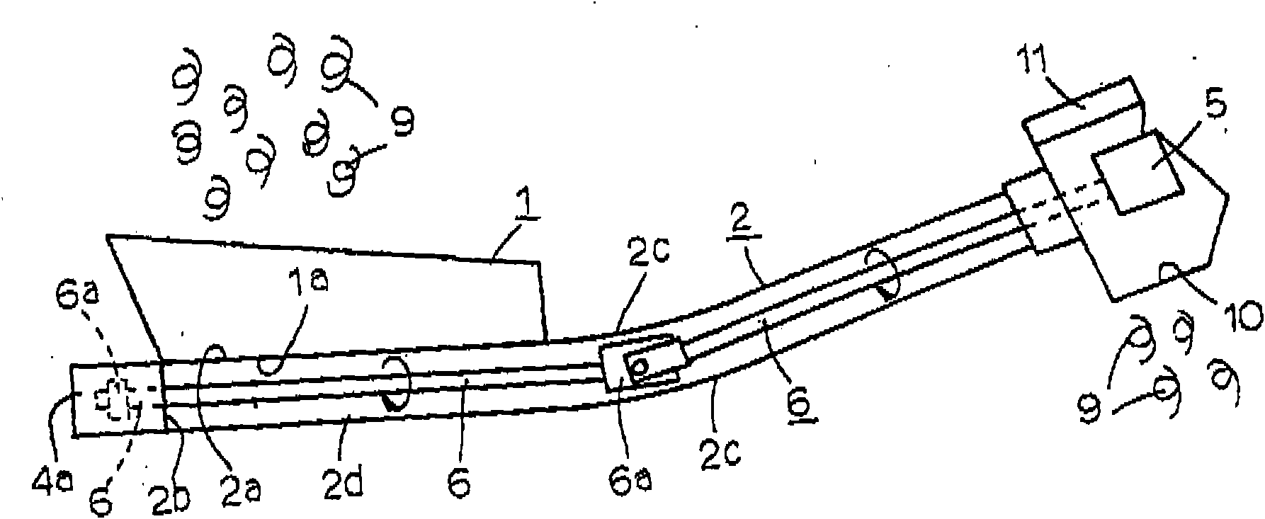
[0023] Next, a more specific embodiment of the overflow coil chip conveyor for separating chips and cutting oil according to the present invention will be described in detail with reference to the accompanying drawings. First, there is a bucket 1 . Next, there is the pipe 2 for the conveyor main body. The pipe 2 has a chip and cutting oil inlet 2a, which is in close contact with the lower opening 1a of the bucket 1, and the vicinity of the chip and cutting oil inlet 2a is horizontal. Furthermore, the front end direction of the pipe 2 is bent upward by 10° to 30°, and the bending radius R thereof is configured to be 500 mm to 1000 mm. In addition, there is a coil 3 for the conveyor main body. The coiled material 3 is accommodated in the tube 2 and extends over the entire length of the tube 2, and the material of the coiled material 3 is composed of piano wire of SWP-B in JIS standard.

[0024] Furthermore, it has the universal joint 4 for coils. One end of the web universal...

Embodiment 2

[0027] In addition, an overflow coil chip conveyor for separating chips and cutting oil according to the present invention will be described in detail using more specific embodiments with reference to the drawings. First, chips 9 and cutting oil 8 generated during the manufacture of mechanical parts (refer to image 3 ) is received and concentrated by bucket 1. The cutting oil 8 in the bucket 1 forms a pool shape, the chips 9 settle, and only the upper layer of the cutting oil 8 exits the cutting oil outlet 7 (refer to figure 1 with 3)overflow. The deposited chips 9 are conveyed by the rotation of the coil 3 , and the coil 3 is rotated by the motor 5 via the spindle 6 . In the control box 11, continuous operation and intermittent operation can be selected. Equipped with a torque limiter unit, the push needle presses the micro switch every time the motor 5 rotates once, and if it is not pressed within a predetermined time, it reverses to remove the overload. If the overloa...


PUM


Abstract

The present invention provides a overflow type material rolling and chipping conveyor that separates cutting scrap with cutting lubricant, which relates to material of material used in adverse environment and a bending structure; a tube (2) is provided with a inlet (2a) of the cutting scrap and the cutting lubricant that stick to opening of a scoop (1); area around the inlet of the cutting scrap and the cutting lubricant is in horizontal status; front-end of the tube bends upwards from 10 DEG to 30 DEG and bending radius R is from 500 mm to 1000 mm. The material covers the tube all over and is collected in the tube, material quality is piano wire of SWP-B of JIS standard. A universal joint combines with one end of the material near to inlet of the cutting scrap and the cutting lubricant, and makes the material rotate. The pipe wall holds the universal joint, and closes end of the tube close to the universal joint. An electric motor makes the universal joint rotates. An outlet of the cutting lubricant is set on above scoop, bottom of the cutting lubricant outlet lies in location of such horizontal plane: cutting lubricant that put into tube through the scoop up to oil mass of bending section of material collected in the tube.

Description

technical field [0001] The present invention broadly relates to a conveyor for cutting chips (swarf) generated during the manufacture of machine parts, and more particularly to an overflow-type coil chip conveyor that separates chips from cutting oil in which the conveying portion is a coil type. The chip conveyor conveys the chips to a predetermined position while separating them from the cutting oil. Background technique [0002] Conventional chip conveyors include a belt conveyor type, a spiral conveyor type, and a rectangular screw conveyor type. Especially in stud conveyors and rectangular screw conveyors, as a driving member, the main shaft is turned and the studs or rectangular screws are rotated to carry out conveyance, but as a chip conveyor, there is no such thing as a chip conveyor that can withstand harsh environments , and the rising part of the cylinder up to the discharge port and the discharge rear part are integrated. [0003] Patent Document 1: Japanese P...

Claims


Application Information

Patent Timeline
Patent Type & Authority Applications(China)
IPC IPC(8): B23Q11/00B65G49/00B65G33/14B65G33/24B65G33/26
CPCB23Q11/02B65G33/08B65G33/10B65G33/26B65G65/30B65G65/46
Inventor 武藤诚典
Owner 武藤 诚典
Learn More