Cutting method of crystalline silicon blocks

A cutting method and technology for silicon blocks, which are used in grinding machines, fine working devices, metal processing equipment, etc., can solve the problem of small silicon fragments falling into the wire saw mesh or guide wheel, reducing the service life of the guide wheel, wire breakage, etc. Jumper and other problems, to achieve the effect of improving the yield of slicing, the quality of silicon wafers, and improving the stability

Inactive Publication Date: 2009-10-14
ZHEJIANG YUHUI SOLAR ENERGY SOURCE
View PDF0 Cites 24 Cited by
  • Summary
  • Abstract
  • Description
  • Claims
  • Application Information

AI Technical Summary

Problems solved by technology

The "climbing" phenomenon of the inclined surface in the slice can easily cause the vibration of the linear sawing net, cause jumping wires, and cause abnormal fluctuations in the linear sawing net as a whole. The vibration of the local linear sawing net near the end face is particularly obvious, usually Many defective chips are generated near the end face
[0006] Second, during the slicing process, it is very easy to produce tiny silicon fragments falling into the wire saw net or the guide wheel, which will also cause wire breakage and jumping, and may also cause damage to the guide wheel and reduce the service life of the guide wheel
In the study of bad pieces at the seams, it was found that if the slope of these seams is too large or not smooth enough during the slicing process, many waste pieces at the end will be produced.
Because the two ends connected at the seam together disturb the slicing process more, not only produce more bad pieces on the end faces, but also greatly affect the overall slicing quality
[0008] There are no special equipment and methods at home and abroad to accurately deal with the problem of end face slope and unevenness. Foreign countries use internal circular cutting machines or precision band saws for cutting processing, but they do not deliberately aim at improving end face verticality, etc. Ways to Improve Slicing Yield
With the rapid development of the silicon wafer manufacturing process, the thickness of the silicon wafer currently accepted by the market is less than 220 microns, while the domestic cutting machine usually causes a slope of more than 500 microns during the segmentation process. And the loss of silicon wafers caused by it is also increasing
The existence of the slope of the end face makes the slope "climbing" or debris during the slicing process unavoidable, which disturbs the entire wire network and affects the slicing quality

Method used


Image

  • Cutting method of crystalline silicon blocks
  • Cutting method of crystalline silicon blocks
  • Cutting method of crystalline silicon blocks

Examples


Embodiment 1

[0027] In this technical scheme, the 264 model slicer of Swiss MB company is used to cut the crystalline silicon block into slices.

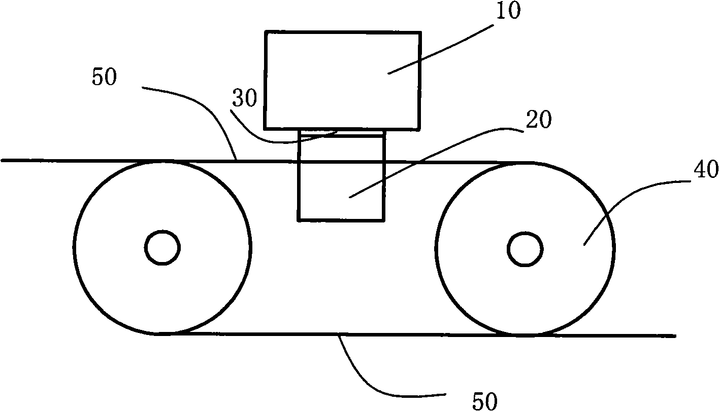
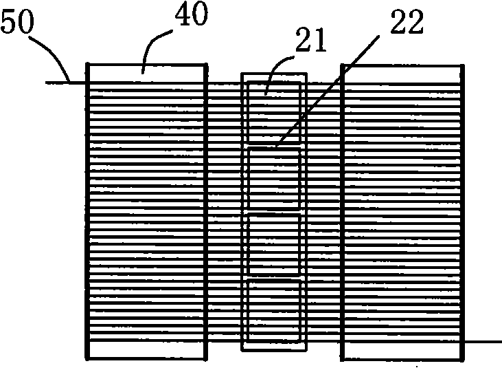
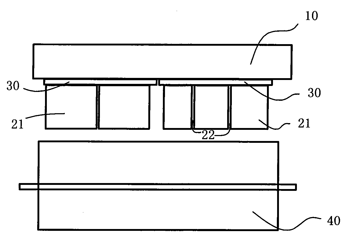
[0028] like figure 1 , figure 2 , image 3 , Figure 4 As shown in the figure, several short silicon blocks 21 of different lengths are sent to the end face grinding CNC machine tool to be ground flat, so that the originally uneven end face 23 is flattened into an end face 24 with an inclination of not more than 200 microns, and then the short silicon blocks with the flat end face are flattened. 21 is glued to the base glass 30, there is a splicing seam 22 in between, and its total effective length is 760mm, and the base glass crystal 30 with the short silicon block 21 glued is installed on the working table 10 of the slicing machine to become a cutting workpiece.

[0029] When slicing is started, the workpiece is slowly pressed down, and the pre-prepared mortar is supplied to the wire saw 50 by the motor. The guide wheel 40 drives the wire ...

Embodiment 2

[0031] like figure 1 , figure 2 , image 3 , Figure 4 As shown, in this technical solution, the 264 model slicer of Swiss MB company is used to cut the crystalline silicon block into slices.

[0032] Several short silicon blocks 21 are directly arranged and glued to the base glass 30, and the crystalline silicon blocks with a total effective length of 760 mm are directly mounted on the worktable 10 of the slicer to become a cutting workpiece.

[0033] When slicing is started, the workpiece is slowly pressed down, and the pre-prepared mortar is supplied to the wire saw 50 by the motor. The guide wheel 40 drives the wire saw to rotate. The silicon block is rubbed at high speed to achieve the purpose of cutting, and the whole slicing process takes 7.5 hours.

Embodiment 3

[0035] like figure 1 , figure 2 , image 3 , Figure 4 As shown, in this technical solution, the crystalline silicon block is cut into slices by using the B5 slicer of HCT Company in Switzerland.

[0036] like figure 1 , figure 2 , image 3 As shown in the figure, several short silicon blocks 21 of different lengths are sent to the end face grinding CNC machine tool to be ground flat, so that the originally uneven end face 23 is flattened into an end face 24 with an inclination of not more than 200 microns, and then the short silicon blocks with the flat end face are flattened. 21 is glued to the base glass 30, leaving a splicing seam 22 in between, and its total effective length is 860 mm. After the base glass crystal 30 glued with the short silicon block 21 is installed on the worktable 10 of the slicer, it becomes a cutting workpiece .

[0037] When slicing is started, the workpiece is slowly pressed down, and the pre-prepared mortar is supplied to the wire saw 50 ...


PUM


Abstract

The invention relates to a cutting method of crystalline silicon blocks, a crystalline silicon block to be cut is placed on a section cutter platform, a plurality of line-shaped saws are horizontally distributed and spray mortar so as to cut the crystalline silicon block; and the method is characterized in that: the two end surfaces of the crystalline silicon block are polished to be level before being cut, and the line-shaped saws are parallelly distributed at equal intervals, with the width of shorter than the length of the crystalline silicon block to be cut. The technical proposal improves the 'climbing' phenomenon in the cutting process of the crystalline silicon block, and well solves the problems of wire-break and line-skipping caused by that silicon fragments generated in the cutting process of the crystalline silicon block drop to the line-shaped saw net or an idler pulley.

Description

technical background [0001] The invention belongs to the technical field of crystalline silicon block processing and silicon wafer preparation, and particularly relates to a polysilicon block cutting method for improving the slicing yield of the crystalline silicon block. Background technique [0002] Crystalline silicon wafers are widely used in the field of microelectronics or solar cells. They are made of silicon materials by Czochralski or ingot casting methods into monocrystalline rods or polycrystalline silicon ingots, cubed, cut into silicon blocks and then sliced. The main working principle of its slicing is to stick silicon blocks of different lengths on a fixed length of viscose glass. The thin steel wire on the guide wheel with fine grooves drives the mortar supplied to the steel wire, and the silicon block is cut by the SiC fine powder in the mortar. [0003] With the rapid development of the solar photovoltaic industry in recent years, the industry has an incre...

Claims


Application Information

Patent Timeline
IPC IPC(8): B28D5/04B24B7/16B24B7/22
Inventor 吴云才刘伟刘文涛聂帅
Owner ZHEJIANG YUHUI SOLAR ENERGY SOURCE
Why Eureka
Try Eureka