Orthophoto pan-tilt-zoom of unmanned plane

A technology of orthophotos and drones, applied to aircraft parts, use feedback control, camera devices, etc., can solve the problems of increasing the difficulty of flight operations, irregular distortion of shooting data, and high cost, so as to reduce repeated positioning inspections , reduce human participation, simple structure effect

Inactive Publication Date: 2009-10-14
董韬
View PDF0 Cites 43 Cited by
  • Summary
  • Abstract
  • Description
  • Claims
  • Application Information

AI Technical Summary

Problems solved by technology

[0002] When the UAV is used in the aerial survey process, due to the small load capacity and the small cabin volume of the UAV, there are usually two ways to install the camera: one is directly installed vertically on the body, and the aircraft is affected by the airflow during the flight operation. , there will be irregular changes in pitch, roll and other attitudes, and the camera optical axis will also change the vertical incidence angle to the ground with the change of aircraft attitude, resulting in irregular distortion of shooting data, and the overlap rate is difficult to guarantee, which increases the difficulty of flight operations , seriously affecting the accuracy and efficiency of aerial survey post-processing
[0003] The second is to use the gimbal control technology, which is mainly divided into two types at present: 1. Use the inclination sensor. The acceleration and vibration of

Method used


Image

  • Orthophoto pan-tilt-zoom of unmanned plane
  • Orthophoto pan-tilt-zoom of unmanned plane
  • Orthophoto pan-tilt-zoom of unmanned plane

Examples


Embodiment Construction

[0022] The present invention will be described in further detail below with reference to the accompanying drawings and specific embodiments.

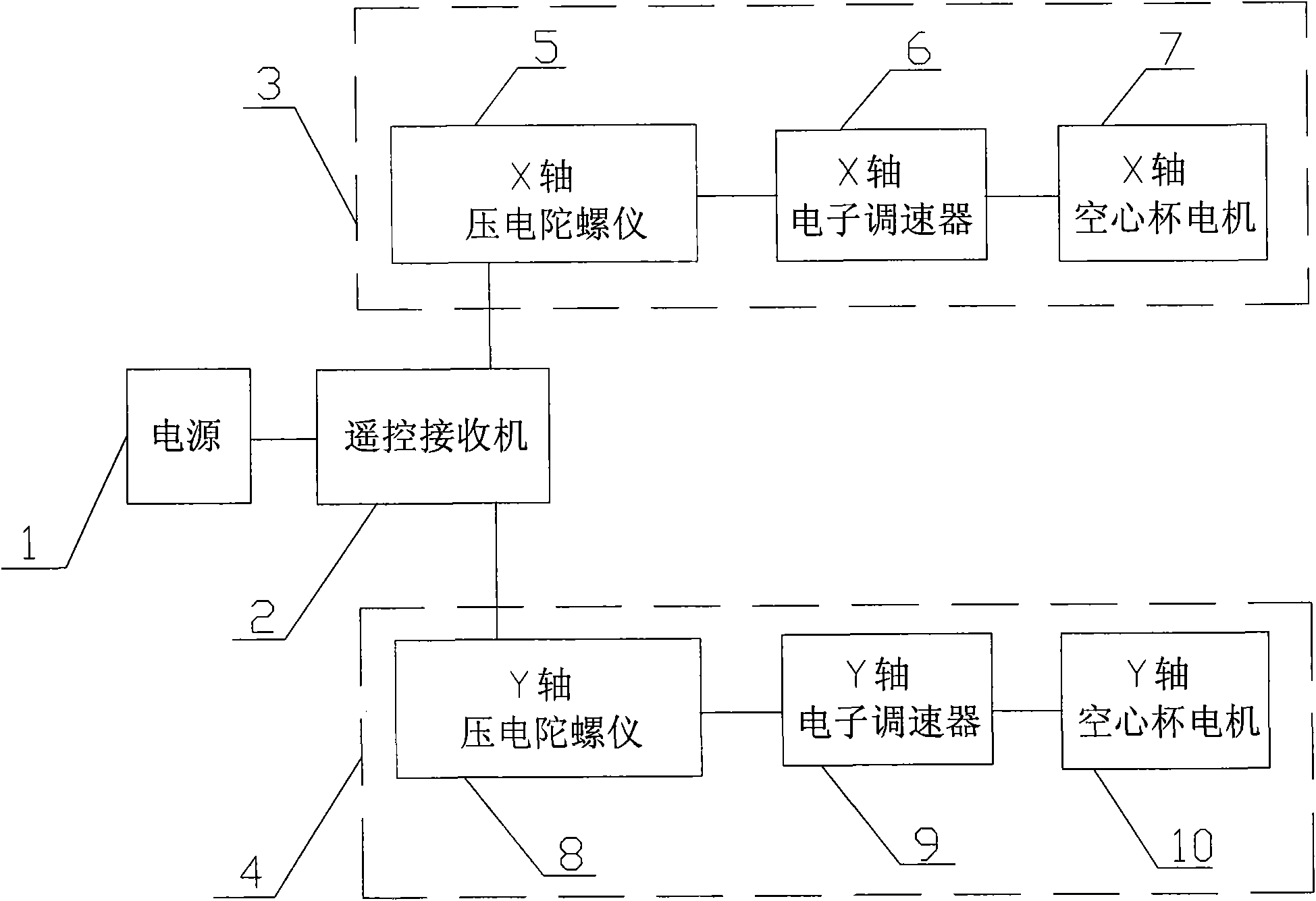
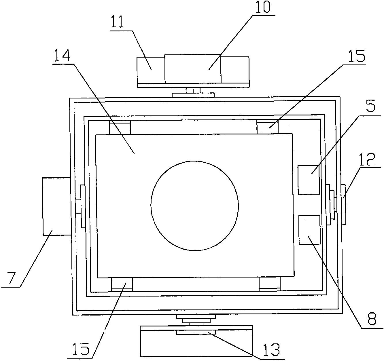
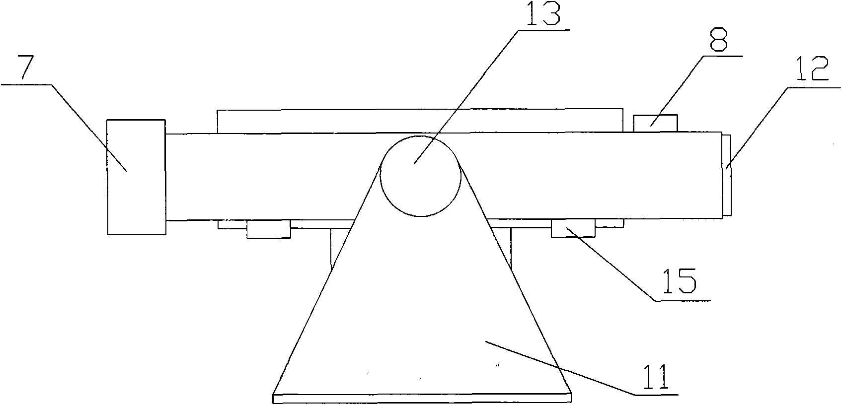
[0023] like Figure 1 to Figure 3 As shown in the figure, the drone orthophoto pan / tilt is assembled on the bottom of the drone through the pan / tilt bracket 11, the camera 14 is mounted on the pan / tilt base via the camera bracket 15, and the base is controlled by the X-axis control group 3 and the Y-axis of the pan / tilt. Control group 4 controls, can rotate in the direction of X axis 12 and Y axis 13 individually or simultaneously.

[0024] The X-axis control group 3 includes an X-axis piezoelectric gyroscope 5 , an X-axis electronic governor 6 and an X-axis hollow cup motor 7 which are connected in sequence. The X-axis piezoelectric gyroscope 5 is installed on the base of the gimbal, and remains relatively stationary with the camera 14 . The input end of the X-axis piezoelectric gyroscope 5 is connected to the remote control receiver...


PUM


Abstract

The invention relates to an orthophoto pan-tilt-zoom of an unmanned plane. A camera is controlled by a control device of the pan-tilt-zoom and is led to keep the optical axis thereof to be vertical with the ground in the flying process, thus improving mapping precision and greatly reducing flying operation time. The orthophoto pan-tilt-zoom of the unmanned plane is assembled at the bottom part of the unmanned plane; the camera is arranged on a base of the pan-tilt-zoom; the base is connected with an X-axis control group and a Y-axis control group of the pan-tilt-zoom; the X-axis control group and the Y-axis control group are respectively comprise a gyro, an electronic speed regulator and a server which are connected in sequence; and the gyro is connected with a remote-control receiver and a power supply in sequence; when the unmanned plane flies, the incidence angle of optical axis of the camera to the ground generates deviation, at the time, the gyro detects deviation rate of the camera and outputs corresponding signals to the electronic speed regulator; the electronic speed regulator controls the server to make corresponding rotation to output opposite moment so as to damp the generation and continuity of deviation of the camera and lead the camera to restore the state vertical to the ground naturally by the center of gravity of the camera.

Description

technical field [0001] The invention belongs to the field of pan-tilt control devices, and in particular relates to a control device for an unmanned aerial vehicle-mounted ortho-image pan-tilt. Background technique [0002] When the drone is used for aerial surveying, due to the small weight of the drone and the small volume of the cabin, there are usually two ways to install the camera: one is to directly install it on the body vertically. During the flight operation, the aircraft is affected by the airflow. , will produce irregular attitude changes such as pitch and roll, and the optical axis of the camera will also change the vertical incidence angle to the ground with the change of the aircraft attitude, resulting in irregular distortion of the shooting data, and the overlapping rate is difficult to guarantee, which increases the difficulty of flight operations. , which seriously affects the accuracy and efficiency of post-processing of aerial surveys. [0003] The seco...

Claims


Application Information

Patent Timeline
IPC IPC(8): B64D47/08G01C11/02G05D3/12
Inventor 董韬
Owner 董韬
Why Eureka
Try Eureka