

Crude oil dehydrating device combing electric field and centrifugal field
A technology of crude oil dehydration and centrifugal field, which is applied in the direction of electric liquid separation, liquid separation, separation methods, etc., can solve the problems of restricting the popularization and application of high-frequency pulse electric field dehydration technology, inconvenient management, large floor area, etc., and achieve improvement Dehydration effect, convenient management, small footprint
- Summary
- Abstract
- Description
- Claims
- Application Information
AI Technical Summary
Problems solved by technology
Method used
Image

Examples
Embodiment Construction
[0022] In order to further disclose the technical solutions of the present invention, the following will be described in detail through examples in conjunction with the accompanying drawings.
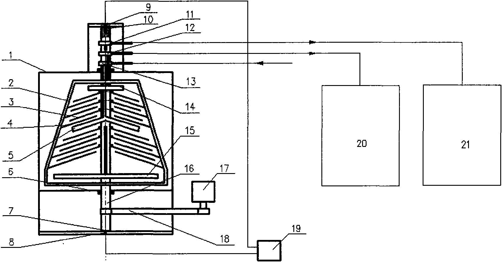
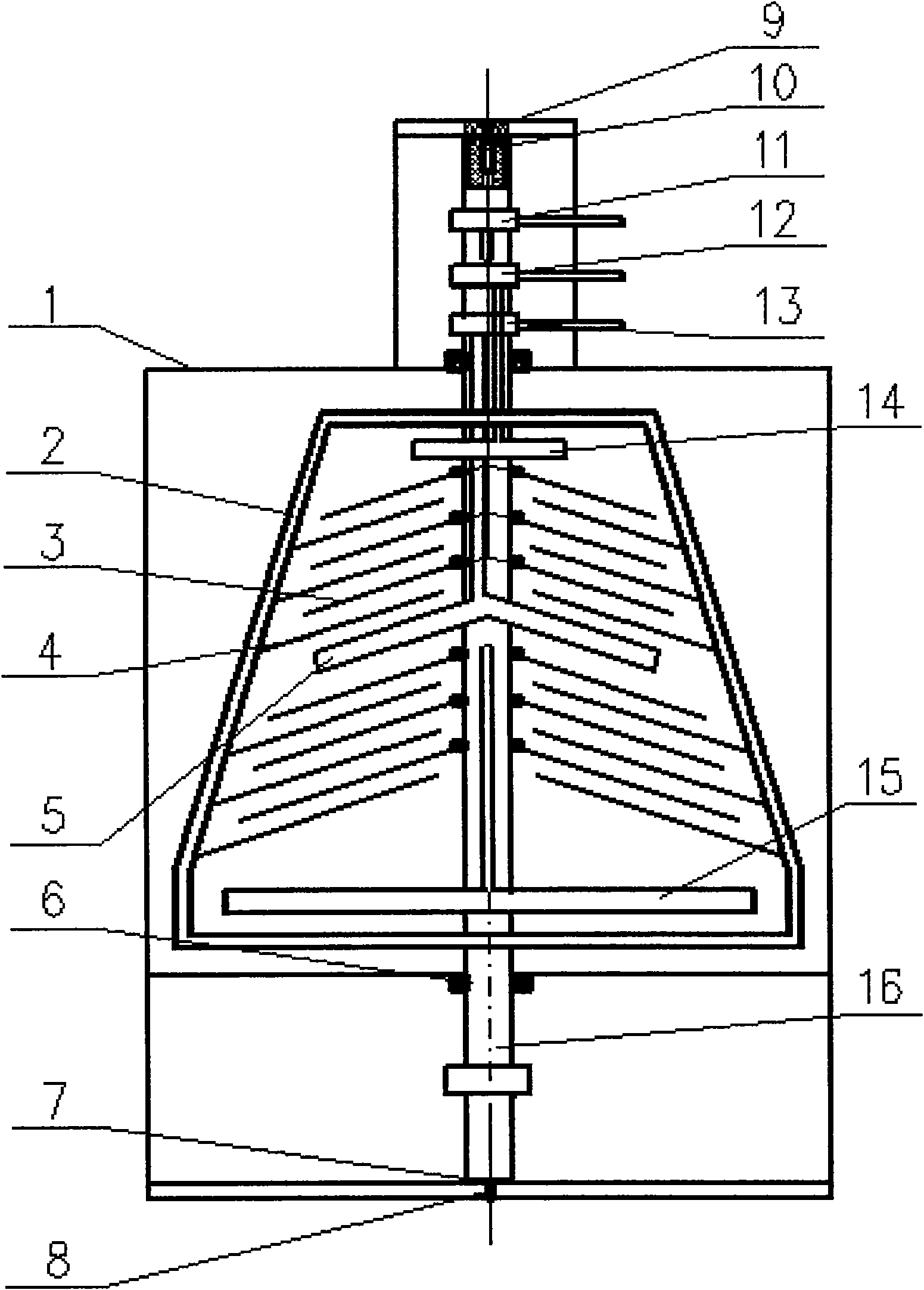
[0023] The present invention is made up of casing 1, electric field and the structure that centrifugal field is set integrally, motor 17, pulley, V-belt 18, dehydration power supply device 19, oil storage tank 20 and sewage tank 21. It is characterized in that the centrifugal field structure consists of a hollow shaft 16 arranged in the vertical center of the casing, a liquid inlet pipe, a water outlet pipe and an oil outlet pipe arranged in the hollow shaft, and a closed conical centrifugal chamber 2 arranged in the middle of the hollow shaft, The upper part of the centrifuge chamber is equipped with a rice-shaped round tube oil collector 14, an umbrella-shaped round tube liquid distributor 5 in the middle, and a rice-shaped round tube water collector 15 in the lower part. The sealing ...
PUM
 Abstract
Description
Claims
Application Information