System for measuring surface bidirectional reflectance distribution

A technology for bidirectional reflection distribution and surface measurement. It is used in measurement devices, optical radiation measurement, photometry, etc. It can solve the problem of inconvenient online measurement and measurement of large target surfaces, inability to measure bidirectional reflection distribution on surfaces, and large repeatability errors. problems, to facilitate online measurement and large target surface measurement, to avoid the interference of retroreflected light, and to achieve the effect of small repeatability error

Inactive Publication Date: 2009-10-28
NORTHWESTERN POLYTECHNICAL UNIV
View PDF1 Cites 19 Cited by
  • Summary
  • Abstract
  • Description
  • Claims
  • Application Information

AI Technical Summary

Problems solved by technology

However, this method has some defects: the measurement accuracy is affected by the diameter of the optical fiber used; the reflection from the end face of the optical fiber will return to the surface of the sample to be measured and interfere with the measurement results; the manufacturing process of the device is relatively complicated; The continuous change of the angle and affects the measurement of backscattering
[0006] It can be seen that the problems of the current device for measuring the bidirectional reflection distribution of the surface mainly include: 1. The measurement of the bidirectional reflection distribution of the surface cannot be completed in a short period of time
2. Large repeatability error
3. Accurate measurement of bidirectional reflection distribution in the entire hemisphere space including backscattering cannot be achieved
4. Unavoidable retroreflected light interference measurement
5. It is not convenient to carry out online measurement and large target surface measurement
6. The manufacturing process of the device is complex

Method used


Image

  • System for measuring surface bidirectional reflectance distribution
  • System for measuring surface bidirectional reflectance distribution
  • System for measuring surface bidirectional reflectance distribution

Examples


Embodiment Construction

[0030] Now in conjunction with embodiment, accompanying drawing, the present invention will be further described:

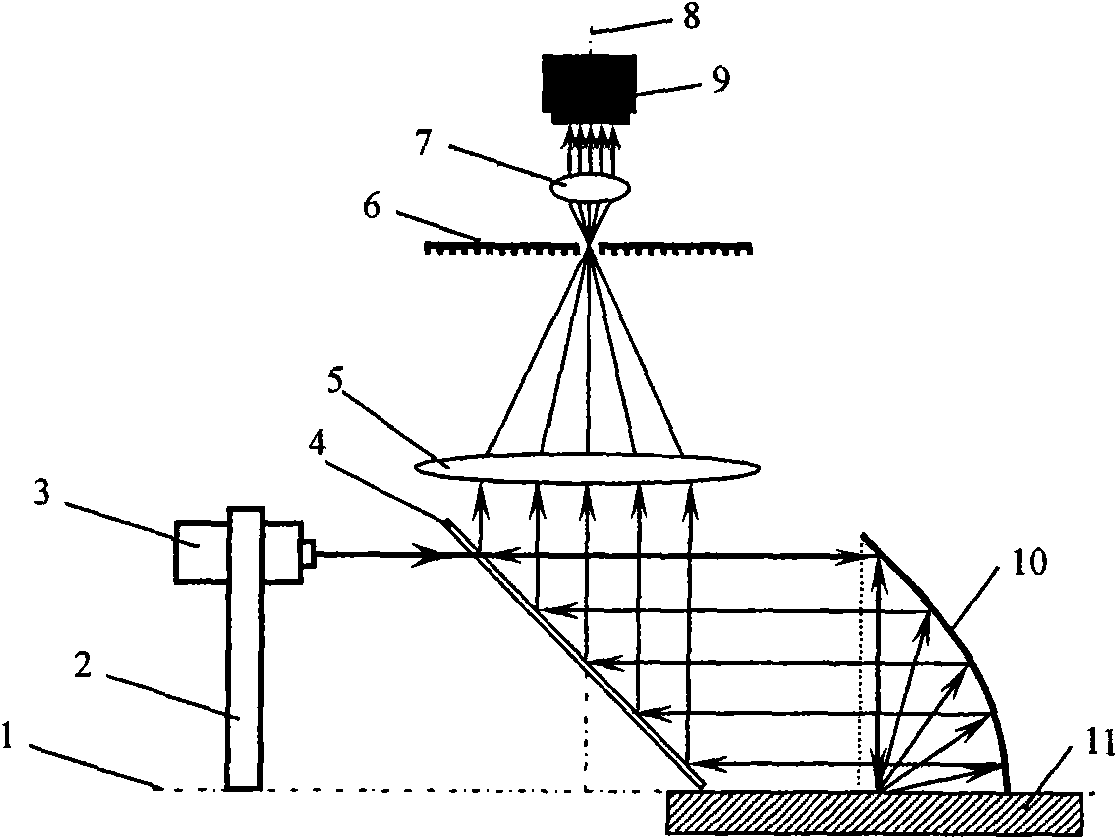
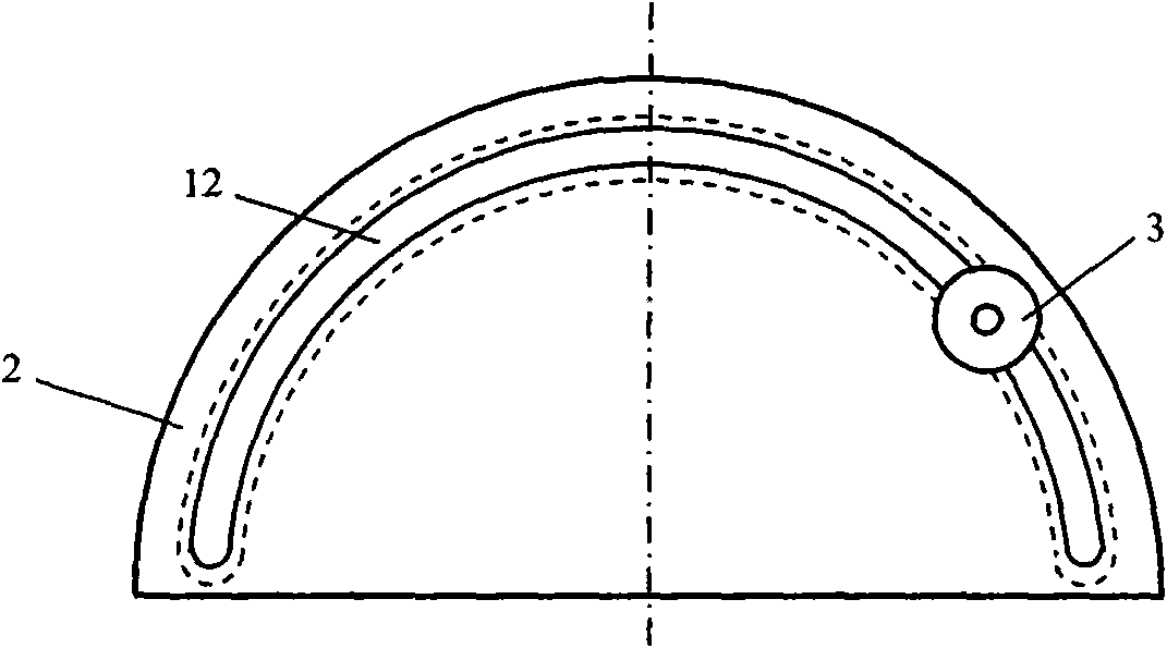
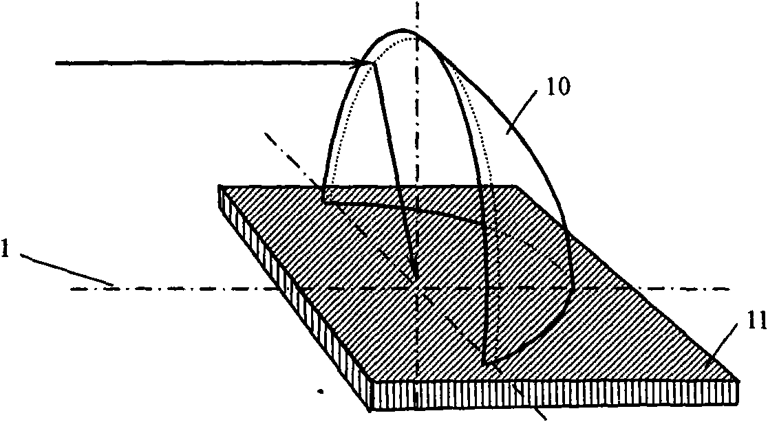
[0031] Such as figure 1 The shown object bidirectional reflection distribution measurement device includes a beam splitter 4, a semi-parabolic mirror 10, a light source system and an imaging system. The beam splitter 4 is fixed between the light source 3 and the parabolic mirror 10, and its normal line forms an angle of 45 degrees with the main axis of the device. The optical axis of the light source 3 is parallel to the main shaft 1 of the device, and the light source 3 is assembled on a semicircular arc slide rail perpendicular to the main shaft 1 of the device, and can rotate around the main shaft 1 of the device. The light source 3 can be a semiconductor laser or other collimated white light source. The light beam emitted by the light source 3 passes through the beam splitter 4, is reflected by the semi-parabolic mirror 10, and converges at its focal point. ...


PUM


Abstract

The invention relates to a system for measuring surface bidirectional reflectance distribution. The system is characterized in that a hemi-parabolic reflector is arranged on the surface of a sample to be measured; a light source system is arranged on one side of a main shaft in the center of the hemi-parabolic reflector, and is opposite to the inner parabolic surface; an imaging system is arranged on a shaft which is intersected with and vertical to the main shaft, and is positioned above a plain shaft; a beam splitter is arranged between the light source system and the hemi-parabolic reflector; the mirror surface of the beam splitter forms a 45-degree angle with the plain shaft; the light source system consists of a light source, a semicircular light source seat and a sliding rail; the radius of the sliding rail is twice of focal distance of a parabolic reflector, and is embedded in the upper edge of the semicircular light source seat; the light source is arranged on the semicircle sliding rail; the plain shaft is parallel to the main shaft; the beam splitter is a half-silvered mirror; the inner surface of the hemi-parabolic reflector is a reflecting coating; and the caliber of the parabolic surface is more than fourfold focal distance. The system can complete measurement of surface bidirectional reflectance distribution in short time, and has smaller repeatability error.

Description

technical field [0001] The invention relates to a system for measuring two-way reflection distribution of a surface, which uses a parabolic reflector to change the direction of light propagation and measures the field of surface scattered light field distribution through an array detector. Background technique [0002] The spatial distribution of the scattered light field on the surface of an object can be described by the Bidirectional Reflectance Distribution Function (BRDF). BRDF records the reflection distribution of the surface of the object to the incident light in different directions at various angles. It is a multivariate function, and the measurement process is complicated. [0003] There are two main types of existing bidirectional reflectance distribution function measurement devices: one is to use one or more photodetectors to perform two-dimensional or one-dimensional mechanical scanning on the surface of the sample to be measured, and to detect the radiation a...

Claims


Application Information

Patent Timeline
Patent Type & Authority Applications(China)
IPC IPC(8): G01J1/00G01J1/04G02B5/10G02B7/00G02B7/182
Inventor 赵建林任驹
Owner NORTHWESTERN POLYTECHNICAL UNIV
Why Eureka
Try Eureka