Laser coating device and method based on transparent material
A transparent material, laser coating technology, applied in the field of micromachining, can solve the problems of high cost, complex coating system process, slow speed, etc., and achieve the effects of low cost, good controllability and simple device
- Summary
- Abstract
- Description
- Claims
- Application Information
AI Technical Summary
Problems solved by technology
Method used
Image
Examples
Embodiment 1
[0047] Example 1: Plating a 100mm*100mm zinc oxide film layer
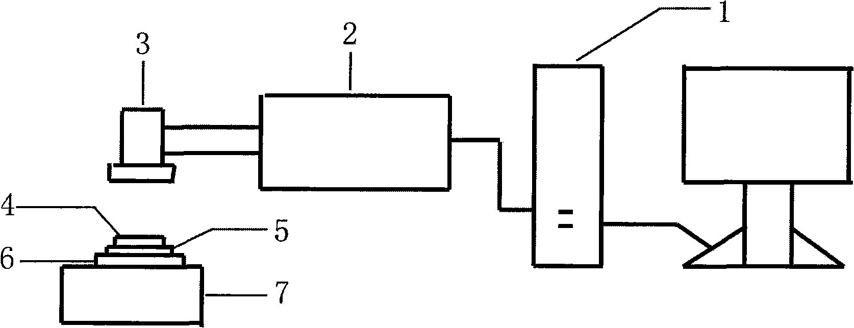
[0048] Spread the zinc powder evenly on the stainless steel plate and compact it to a thickness of 1mm, and then place a glass plate with a thickness of 3mm on it, keeping the upper surface of the powder layer and the focus of the scanning galvanometer in the same plane. Edit the black fill bitmap with the actual size of 100*100mm in the computer software that controls the laser output, and set the processing parameters as power 10W, frequency 80KHZ, scanning interval 0.1mm, scanning speed 400mm / s. Turn on the laser to make the laser scan according to the set processing parameters. After scanning, use a blower to blow off the powder that has not been irradiated by the laser and adhere to the glass plate and clean it with alcohol. A low-thickness, opaque zinc oxide film can be obtained on the surface of the glass substrate.
Embodiment 2
[0049]Example 2: Making exquisite patterns
[0050] Spread the zinc powder evenly on the stainless steel plate and compact it to a thickness of 1mm, and then place a glass plate with a thickness of 3mm on it, keeping the upper surface of the powder layer and the focus of the scanning galvanometer in the same plane. Edit the bitmap of the snowflake shape in the computer software that controls the laser output, and set the processing parameters as power 10W, frequency 80KHZ, scanning interval 0.1mm, and scanning speed 400mm / s. Turn on the laser to scan the laser according to the set processing parameters. After scanning, use a hair dryer to blow off the powder that has not been irradiated by the laser and adhere to the glass plate and rinse with water to obtain a clear and beautiful snowflake pattern on the surface of the glass substrate.
Embodiment 3
[0051] Example 3: Laser wiring
[0052] Spread the zinc powder evenly on the stainless steel plate and compact it to a thickness of 1mm, and then place a glass plate with a thickness of 3mm on it, keeping the upper surface of the powder layer and the focus of the scanning galvanometer in the same plane. Edit the vector diagram of the thin line shape in the computer software that controls the laser output, and set the processing parameters as power 10W, frequency 80KHZ, and scanning speed 500mm / s. Turn on the laser to scan the laser according to the set processing parameters. After scanning, use a blower to blow off the powder that has not been irradiated by the laser and adhere to the glass plate and rinse with water. Then, fine lines with a line width of micrometers can be obtained on the surface of the glass substrate.
PUM
 Abstract
Description
Claims
Application Information
 - R&D
- Intellectual Property
- Life Sciences
- Materials
- Tech Scout
- Unparalleled Data Quality
- Higher Quality Content
- 60% Fewer Hallucinations
Browse by: Latest US Patents, China's latest patents, Technical Efficacy Thesaurus, Application Domain, Technology Topic, Popular Technical Reports.
© 2025 PatSnap. All rights reserved.Legal|Privacy policy|Modern Slavery Act Transparency Statement|Sitemap|About US| Contact US: help@patsnap.com

