
Hydrogen selective catalytic reduction device and control method thereof

A control method and selective technology, applied in the direction of electronic control of exhaust treatment devices, exhaust devices, noise reduction devices, etc., can solve the problems of three-way catalytic converter failure, application difficulties, heating, etc.

Inactive Publication Date: 2009-11-11
HARBIN ENG UNIV
View PDF0 Cites 12 Cited by
  • Summary
  • Abstract
  • Description
  • Claims
  • Application Information

AI Technical Summary

Problems solved by technology

Diesel engines and ignition lean-burn engines have received great attention from many countries because of their remarkable fuel-saving effects and good environmental performance. In order to make diesel engine emissions meet the requirements of future emission regulations, internal combustion engine workers have proposed various technical solutions. +The technical solution of Selective Catalytic Reduction (SCR) can effectively control NOx and PM emissions. The principle is that through the optimization of the combustion system, PM can be controlled during the combustion process, and the NOx emissions produced can be passed to the exhaust gas. Inject the blue solution with a concentration of 32.5% in the tube as a reducing agent for selective catalytic reduction, this method can make the NOx conversion efficiency above 85%; Ineffective, NOx emissions cannot be effectively controlled, so the SCR technology route similar to diesel engines can also be adopted, but there are some problems in using urea solution as a reducing agent, such as urea solution is corrosive to a certain extent, and has a pungent smell at the same time, adding The blue solution is easy to freeze when the temperature is lower than -11°C, so there will be some difficulties in application in cold regions, and additional heating is required

Method used


Image

  • Hydrogen selective catalytic reduction device and control method thereof

Examples


Embodiment Construction

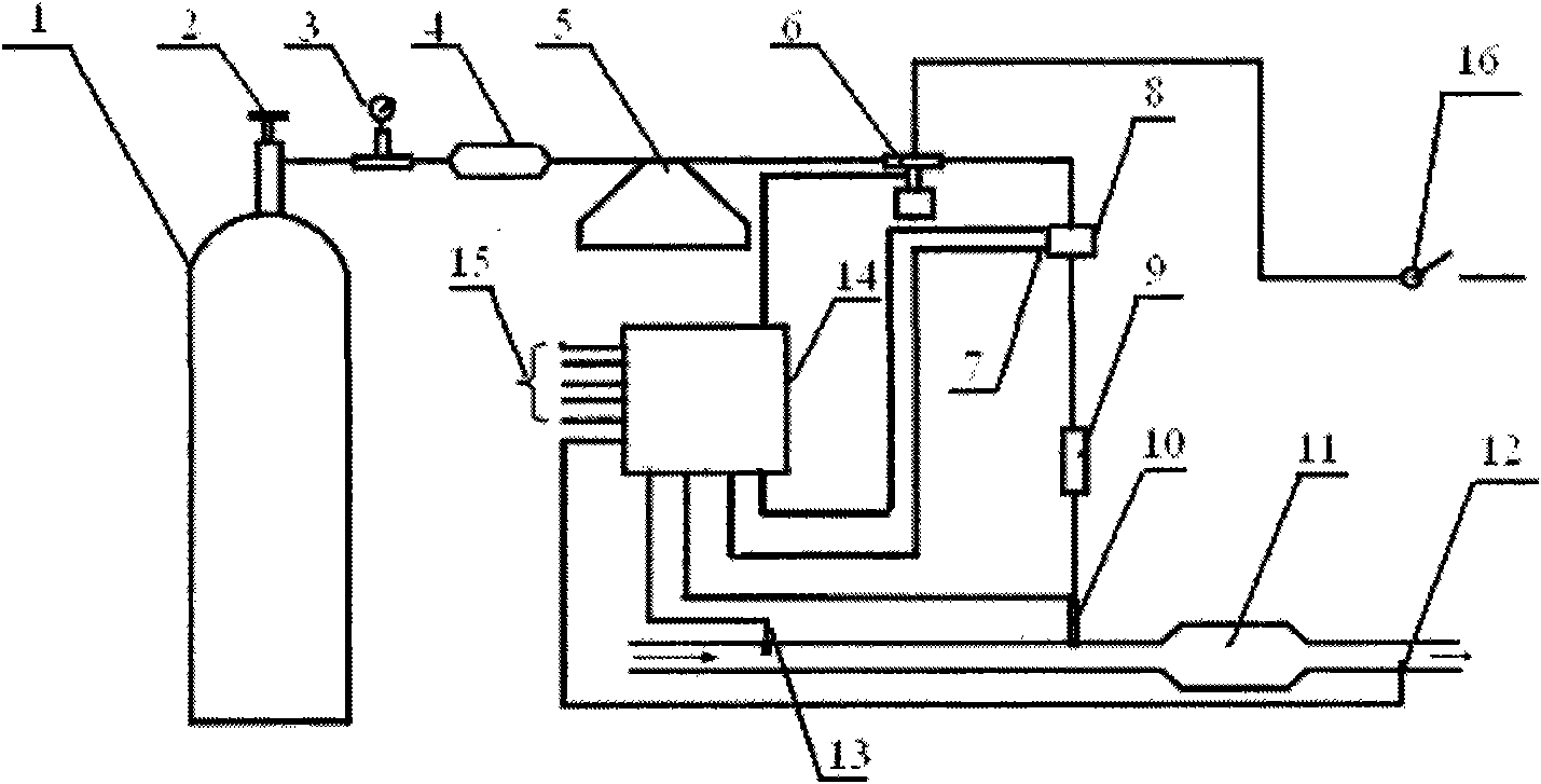
[0009] The present invention is described in more detail below in conjunction with accompanying drawing example:

[0010] a H 2 -SCR system consists of high-pressure gas cylinder 1, manual valve 2, pressure gauge 3, gas filter 4, hydrogen flow meter 5, high-pressure solenoid valve 6, gas temperature and pressure sensor 7, pressure reducer 8, and tempering controller 9. A hydrogen gas injection valve 10, a post-catalysis processor 11, a post-catalysis NOx concentration sensor 12, a pre-catalysis NOx concentration sensor 13 and an electronic control unit 14. Hydrogen is stored in the high-pressure hydrogen cylinder 1 at a pressure of 20 MPa. During the calibration test, firstly open the manual valve 2 to supply air to the system, open the key door 16 to start the engine, and simultaneously open the high-pressure solenoid valve 6 to supply air to the H 2 - The electronic control unit 14 of the SCR system supplies power, and the electronic control unit 14 determines the working s...


PUM


Abstract

The invention provides a hydrogen selective catalytic reduction device and a control method thereof. The device comprises a high-pressure gas storing device, a filtering device, a pressure reducing device, a flow measuring device, an electrical control unit, a performer and various sensors. The electrical control unit judges the working status of a motor and extraction flow based on the signals of the sensors such as intake pressure, intake temperature, the location of an air throttle, rotary speed, top center, oxygen concentration and the like, measures the concentration of NOx in the front discharge pipe of the catalyzing device by an NOx sensor, judges the ejecting impulse width of hydrogen based on the pressure and temperature of a hydrogen supply system and adjusts the hydrogen ejecting volume based on the concentration of collected NOx in the rear discharge pipe of the catalyzing device, thus ensuring the transformation efficiency of NOx reaches the target control value and the ejecting timing of the ejected gas and the ejecting volume MAP are stored in the electrical control unit. The research results of the lean-burn natural gas motor show: the NOx transformation efficiency can reach 100 percent by ejecting hydrogen into the discharge pipe under different operational conditions of a motor.

Description

(1) Technical field [0001] The invention relates to a device for controlling harmful gas emission of an engine, and also relates to a control method of the device. Specifically relate to a hydrogen selective catalytic reduction (H 2 -SCR) device and control method. (2) Background technology [0002] The rapid development of the automobile industry has brought great convenience to people's production and life, but it has also caused serious oil shortages and environmental pollution problems. Countries around the world have successively formulated more and more stringent fuel economy and emission regulations. Automobile manufacturing In order to meet the requirements of these regulations and remain invincible in the fierce market competition, manufacturers actively develop engine energy-saving technologies, explore clean petroleum alternative energy sources, and develop efficient exhaust after-treatment devices. Diesel engines and ignition lean-burn engines have received gre...

Claims


Application Information

Patent Timeline
IPC IPC(8): F01N9/00F01N3/36
CPCY02T10/47Y02T10/40
Inventor 杨立平马修真宋恩哲李文辉李君
Owner HARBIN ENG UNIV
Learn More