Nonmagnetic bimetallic strip driver used in transmission electron microscope

A technology of bimetal sheet and transmission electron microscope, applied in electromagnetic relays, electromagnetic relay details, relays, etc., can solve problems such as hazards, influence of electron microscopes, inconvenience of observation and shooting, etc., and achieve the effect of wide application range and rich research objects

Active Publication Date: 2009-11-18
BEIJING UNIV OF TECH
View PDF0 Cites 5 Cited by
  • Summary
  • Abstract
  • Description
  • Claims
  • Application Information

AI Technical Summary

Problems solved by technology

At present, in the transmission electron microscope, the space between the sample stage and the pole piece is extremely limited, generally 1-3mm, and it is very difficult to manipulate and directly measure the mechanical properties of a single nanowire or nanofilm at atomic scale resolution, and due to As the generating part of the driving force, the bimetal sheet is generally made of magnetic materials such as Fe, Ni, Mn, etc. The thickness of the bimetal sheet is generally on the order of millimeters, and a strong magnetic field is generated in the transmission electron microscope. The magnetic field generated by the magnetic material is opposite to the pole piece. The influence of the electromagnetic field in the medium is very large, and the electron beam is therefore deviated. Sometimes the influence of the magnetic field cannot be eliminated through the adjustment of the astigmatism, so that the atomic-scale information of the monomer nanomaterial cannot be obtained.
In addition, during the specific experimental process in the transmission electron microscope, when observing the sample, with the movement of the bimetallic sheet, the electron beam transmission spot also moves, which will bring inconvenience to the observation and shooting during the experiment. The bimetallic piece is adsorbed to the pole piece, which will have a fatal impact on the electron microscope, causing great harm

Method used


Image

  • Nonmagnetic bimetallic strip driver used in transmission electron microscope
  • Nonmagnetic bimetallic strip driver used in transmission electron microscope
  • Nonmagnetic bimetallic strip driver used in transmission electron microscope

Examples


Embodiment Construction

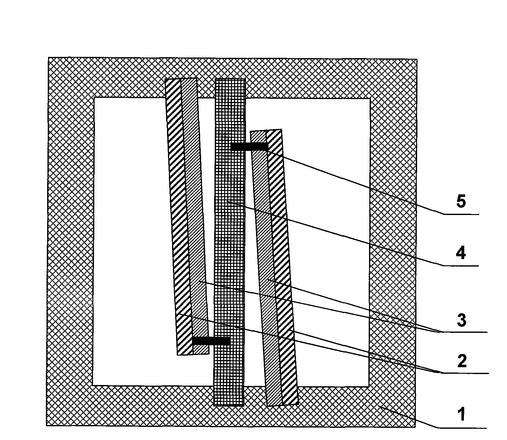
[0019] The device from bottom to top is: metal heat conduction frame with a thickness of 150um and a side length of 2.15mm. The non-magnetic single metal sheet is copper, with a thickness of 100um, a width of 300um, and a length of 2.5mm. The non-magnetic bimetal sheet is made of aluminum-magnesium alloy with a large linear expansion coefficient and bronze with a small linear expansion coefficient. The parts with large linear expansion coefficients of the two non-magnetic bimetal sheets are close to the two non-magnetic In the gaps between the bimetal sheets, the ones with the smallest coefficient of linear expansion are on the outside. The thickness of the non-magnetic bimetal sheets is 100um, the width is 350um, and the length is 2mm. Both ends of the non-magnetic single metal sheet are fixed on the opposite metal heat conduction frame, two non-magnetic bimetal sheets are arranged in parallel and fixed on the metal heat conduction frame, and one end of each non-magnetic bime...


PUM


Abstract

The invention relates to a nonmagnetic bimetallic strip driver used in a transmission electron microscope, which comprises a nonmagnetic signal metallic strip, a nonmagnetic bimetallic strip and a heat conducting metal frame and is characterized in that the nonmagnetic bimetallic strip formed by a nonmagnetic metallic strip with small linear expansion coefficients and a nonmagnetic metallic strip with big linear expansion coefficients is fixed above the heat conducting metal frame; the nonmagnetic signal metallic strip is positioned between the two nonmagnetic metallic strips; nanophase materials are positioned above the nonmagnetic bimetallic strip and placed into the transmission electron microscope to be heated, and then the nonmagnetic bimetallic strip deforms to drive the nanophase materials to deform. The driver excludes the influence of the magnetism of the bimetallic strip on the nanophase materials in the transmission electron microscope and can conveniently and fast obtain the atomic size information of the nanophase materials.

Description

Technical field: [0001] The invention relates to a non-magnetic bimetal driver for a transmission electron microscope, more specifically a non-magnetic bimetal driver driven by heating that eliminates the magnetic influence of the bimetal, and can test monomer nanomaterials in situ and in real time from the atomic scale Apparatus and method for dynamic change process. Background technique: [0002] The transmission electron microscope is one of the most powerful research tools in the field of nanoscience and technology. The sample holder of the transmission electron microscope is used to support the sample to be tested. As the basic structural unit of devices, nanomaterials carry important functions such as support and transmission. People's understanding of the important role of nanomaterials is getting deeper and deeper. Under the action of the stress field, it is very important to study the influence of the dynamic change of its atomic scale on the mechanical properties ...

Claims


Application Information

Patent Timeline
IPC IPC(8): H01J37/02B81B5/00H01J37/26G01B11/16
Inventor 韩晓东刘攀张跃飞邓青松张泽
Owner BEIJING UNIV OF TECH
Why Eureka
Try Eureka