Welding rod for welding hard alloy and steel parts and welding method thereof

A technology of hard alloy and welding rod, applied in the direction of welding medium, welding accessories, welding/cutting medium/material, etc., can solve the problems of increased risk and low efficiency, and achieve the effect of stable arc, beautiful shape and good welding process performance

Inactive Publication Date: 2009-11-25
WUHAN MARINE MACHINERY PLANT
View PDF0 Cites 12 Cited by
  • Summary
  • Abstract
  • Description
  • Claims
  • Application Information

AI Technical Summary

Problems solved by technology

The traditional iron furnace opening drill uses steel parts as the drill body, and the hard alloy sheet is embedded in the tip of the drill body by brazing at the working part of the drill tip. The solder used for brazing is mainly copper powder, lead powder, etc. Melting-point metals are heated by high-frequency heating, and the carbide sheet is embedded in the tip of the drill body with molten solder. During the opening process of the blast furnace, the drill is impacted, squeezed and rotated at high speed, and the deeper the furnace wall, the higher the temperature , the temperature of the drill bit is getting higher and higher when it is working, once it reaches the melting temperature of the filling metal, the hard alloy sheet will fall off, and the drill bit will be replaced many times during the opening process of the iron furnace, which will increase the danger and inefficiency in the production process

Method used


Image

  • Welding rod for welding hard alloy and steel parts and welding method thereof
  • Welding rod for welding hard alloy and steel parts and welding method thereof
  • Welding rod for welding hard alloy and steel parts and welding method thereof

Examples


Embodiment 1

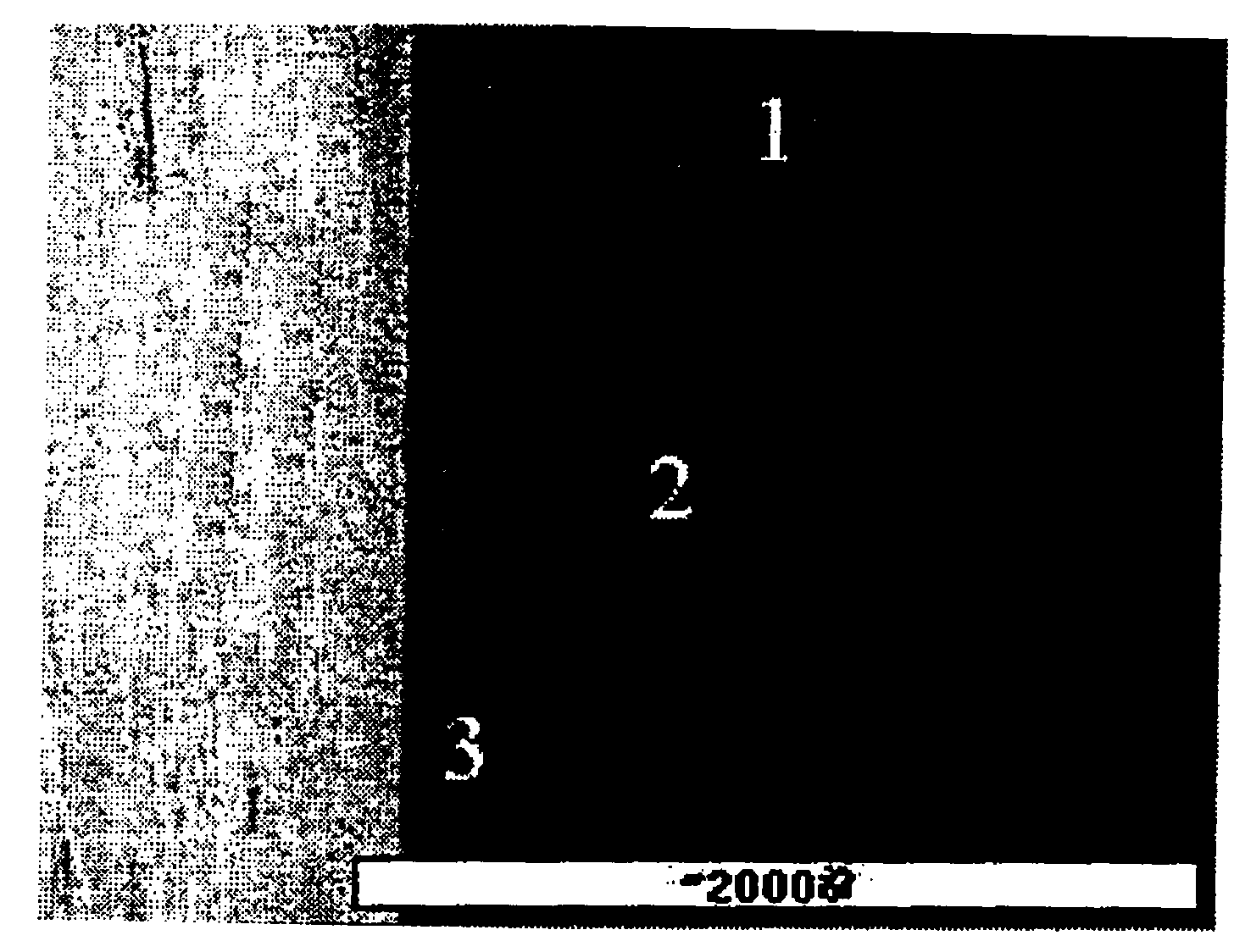
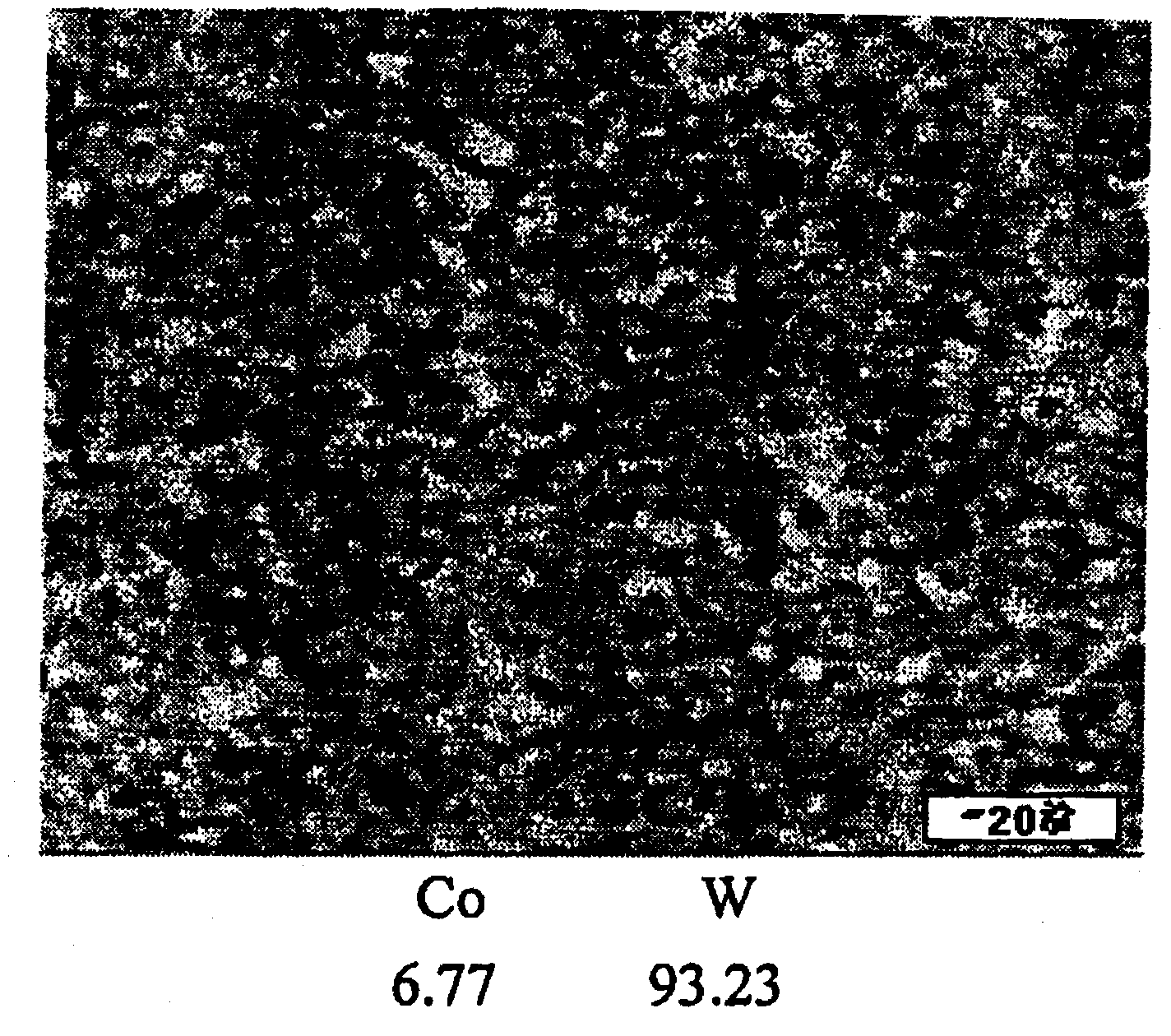
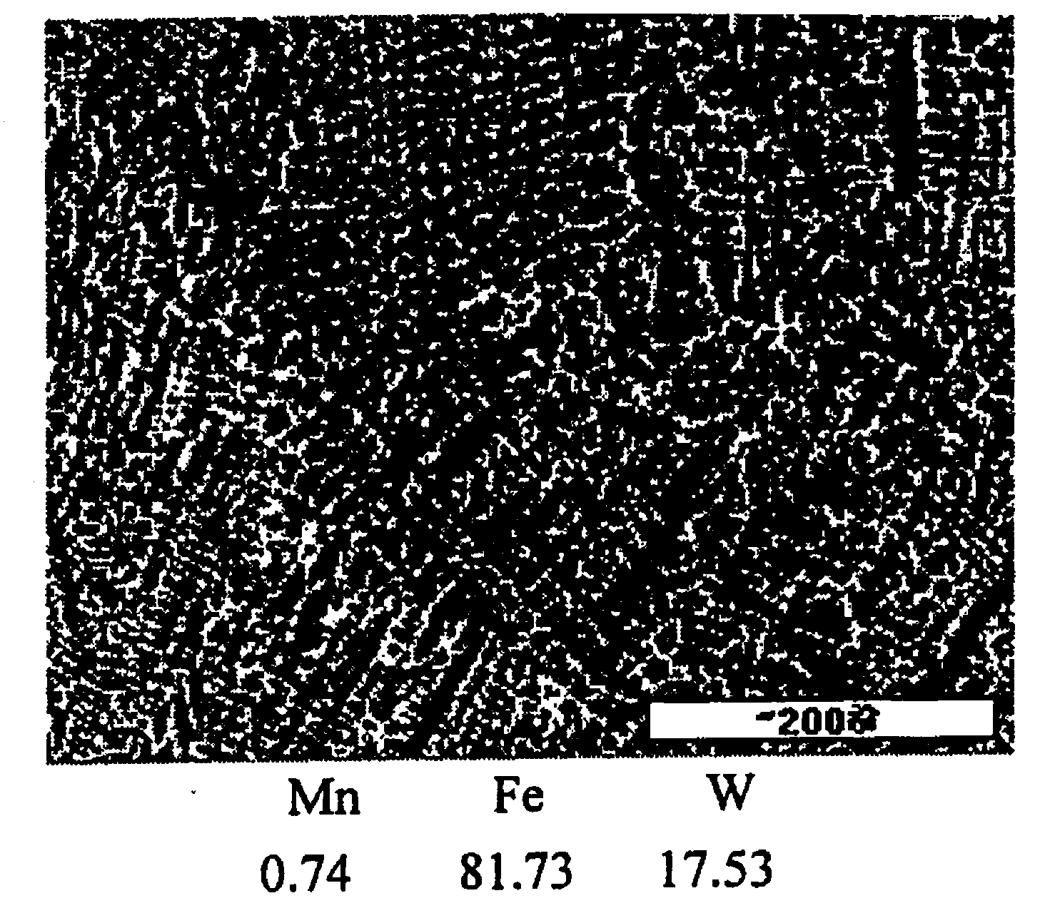
[0022] According to the composition range of the coating of the present invention, the welding rod is prepared, and the specific formula by weight is: W: 51, C: 3, CaCO 3 : 24, CaF 2 : 11, SiO 2 : 3, TiO 2 : 3, rare earth: 1.5, iron powder: 3.5. By welding the 40SiMn cast steel drill body and the cemented carbide sheet, the cemented carbide sheet and the cast steel drill body are welded. The microscopic morphology of the weld after welding is shown in Fig. Figure 1 to Figure 5 .

Embodiment 2

[0024] According to the composition range of the coating of the present invention, the welding rod is prepared, and the specific formula by weight is: W: 52, C: 2, CaCO 3 : 27, CaF 2 : 9, SiO 2 : 4, TiO 2 : 3, rare earth: 1.5, iron powder: 1.5.

Embodiment 3

[0026] Weld the above welding rod on the 40SiMn cast steel drill bit body and the hard alloy sheet. The welding method is to preheat the steel parts in a box-type heating furnace to 400°C-450°C before welding, and heat the hard alloy sheet 15 minutes before welding. Put it in the furnace and preheat it to 250°C-300°C, use an ordinary DC welding machine, and the welding current is: 120A~140A. Immediately after welding, place the welded piece in an incubator at about 300°C, and use the waste heat of the workpiece to keep it warm , the workpiece is naturally cooled in the incubator until it is taken out at room temperature. It can weld the cemented carbide sheet with the cast steel drill bit body. The machining requirements for the drill trouser body (cutter body) are not high during welding. The welding part can even be cast and formed at one time. The welding metal temperature is 500-600 °C It has red hardness and resistance under high temperature, and the welding process perfo...


PUM


Abstract

The invention is a welding rod for welding hard alloy and steel parts and welding method thereof, belonging to the field of welding material. The invention is characterized in that the coating compositions of the welding rod according to parts by weight are as follows: 50 to 53 parts of W, 24 to 27 parts of CaCO3, 9 to 12 parts of CaF2, 2 to 4 parts of TiO2, 2 to 4 parts of SiO, 2 to 4 parts of C, 1.5 parts of rare earth, and remainder being iron powder. The welding metal in the invention has red hardness and endurance at the temperature of 500 to 600 DEG C, thereby solving the welding problem applied between alloy and steel at high temperature; the welding rod has good welding technological property, stable electric arc and beautiful modeling.

Description

technical field [0001] The invention relates to a welding material, more specifically to a welding material and a welding method for welding between Co-W series hard alloys and common steel parts or cast steel parts. Background technique [0002] The ironmaking blast furnace of the iron and steel company needs to use a drill to drill through the furnace wall when pouring molten iron, so that the iron furnace can enter the opening and release the molten iron within the specified time to ensure safety. Temperature, it is required that the drill bit can still work normally under the condition of 500 ℃ ~ 600 ℃. The traditional iron furnace opening drill uses steel parts as the drill body, and the hard alloy sheet is embedded in the tip of the drill body by brazing at the working part of the drill tip. The solder used for brazing is mainly copper powder, lead powder, etc. Melting point metals are heated by high frequency, and the molten brazing material is used to inlay the hard...

Claims


Application Information

Patent Timeline
Patent Type & Authority Applications(China)
IPC IPC(8): B23K35/22B23K9/00B23K9/095B23K9/235B23K9/32B23K35/12B23K35/30
Inventor 李重吴军
Owner WUHAN MARINE MACHINERY PLANT
Why Eureka
Try Eureka