
Runner humidifying vertical plasma and photocatalytic air purifying device

An air purification device and plasma technology, which are applied in air humidification systems, heating methods, separation methods, etc., can solve problems such as reduction, and achieve the effects of simplifying equipment structure, increasing plasma concentration, and improving purification degree.

Inactive Publication Date: 2009-12-02
北京道顺国际技术开发有限责任公司
View PDF0 Cites 2 Cited by
  • Summary
  • Abstract
  • Description
  • Claims
  • Application Information

AI Technical Summary

Problems solved by technology

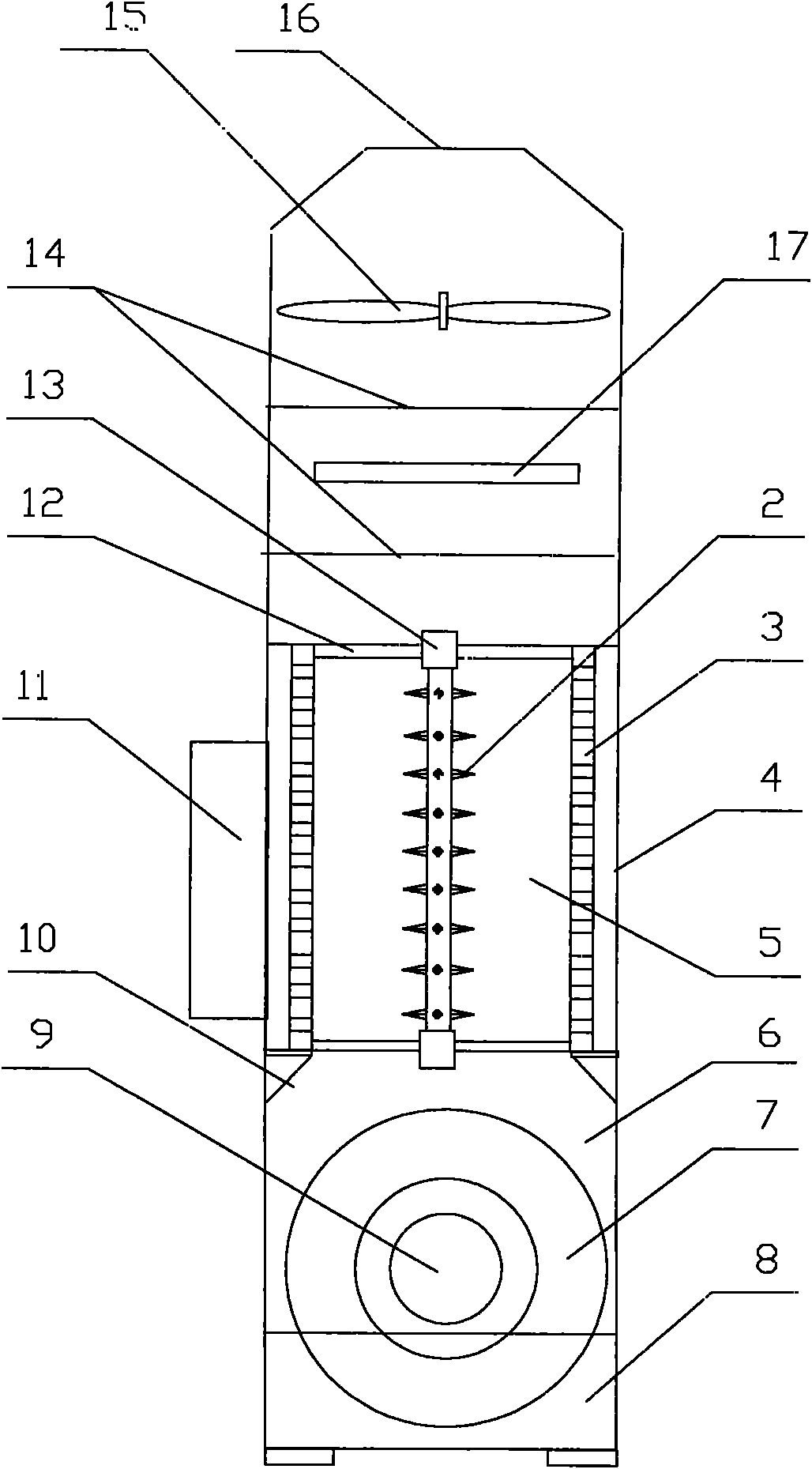
[0007] Since the invention sets the ground electrode in a cylindrical shape and installs the discharge electrode on the axis of the cylindrical ground electrode, the uniformity of the electric field is ensured, and good ionization can be generated in the entire ionization space, and it is not easy to occur due to local shocks. The phenomenon of destroying the overall discharge due to penetration, the space in the cylindrical ground electrode constitutes the air flow channel of the plasma purification chamber; because the uniformly distributed discharge thorns are arranged on the discharge electrode, it is helpful to form a strong electric field near the discharge thorns, In order to ionize the water molecules in the air, a good ionization is formed at a lower voltage, so as to avoid the harsh requirements on insulation, anti-creepage and air parameters due to excessive voltage requirements, which is beneficial to Simplify the equipment structure; because the discharge thorns are evenly distributed on the discharge electrode, it is beneficial to the discharge and ionization everywhere, forming a higher plasma density to speed up the purification speed and improve the purification effect; The wheel humidification chamber is installed, which reduces the concentration of pollutants in the air, increases the water content in the air, helps to improve the ionization characteristics in the plasma purification chamber, increases the plasma concentration, and reduces the pollutant load of plasma purification. , to improve the degree of purification; because the air inlet is connected to the space in the middle of the humidification runner, the air enters the middle space of the humidification runner from the air inlet, turns upwards, passes through the side wall of the humidification runner, and passes through the humidification runner. When the porous material on the side wall of the runner is wet, it collides with the water film attached to the porous material, the pollutant particles in the air and the organic matter that can dissolve into the water are adsorbed by the water, and part of the water vapor enters the air flow, thus The humidification and preliminary purification of the air are realized; due to the relatively strong impact resistance of this wet purification method, the pollution level in the air can still be controlled within a certain range in the case of changes in the concentration of pollutants. This ensures the reliability of the purifier and improves the adaptability; due to this humidification method, more water vapor enters the air flow when the air is dry, and less water vapor enters the air when the air is humid, and even no longer flows into the air. Water vapor (dynamic balance) is diffused in the air, thereby realizing the automatic adjustment of air humidity, and there will be no over-humidification phenomenon like the existing air humidifier; The lamp and the photocatalytic filter can further decompose the residual volatile organic gases through photocatalytic oxidation, so that the air can be further purified, which helps to improve the purification ability and reduce the volume and cost of the equipment

Method used


Image

  • Runner humidifying vertical plasma and photocatalytic air purifying device

Examples


Embodiment Construction

[0009] see figure 1 , the present invention provides a vertical plasma and photocatalytic air purification device for humidity control with a wheel, comprising a housing 4, which is divided into a wheel humidification chamber 6 and a plasma purification chamber 5 from bottom to top in sequence, The humidification chamber of the runner is provided with an annular humidification runner 7, and the bottom is a water tank 8 that can immerse the bottom of the humidification runner. The plasma purification chamber is provided with a ground electrode 3 and a discharge electrode 1. The pole is cylindrical and connected to the power supply ground. The discharge electrode is rod-shaped, with a number of discharge thorns 2 evenly distributed on the surface, connected to the output end of the high-frequency power supply 11. The ground electrode and the discharge electrode are installed together through an insulating bracket 12. A photocatalytic ultraviolet lamp 17 is provided in the photoc...


PUM


Abstract

The invention relates to a runner humidifying vertical plasma and photocatalytic air purifying device, comprising a shell body; wherein, the shell body is internally provided with a runner humidifying chamber, a plasma purifying chamber and a photocatalytic reaction chamber from the bottom up in turn; the runner humidifying chamber is internally provided with an annular humidifying runner, and the bottom thereof is a water tank which can submerge the bottom of the humidifying runner; the plasma purifying chamber is internally provided with an earthing electrode and a discharge electrode; the earthing electrode is barrel-shaped and is connected with a power ground; the discharge electrode is baculiform, and the surface thereof is evenly provided with a plurality of discharge pricks; the discharge electrode is connected with an output end of a high-frequency power supply; the earthing electrode and the discharge electrode are arranged together by an insulated bracket; the photocatalyst filter can be made from reticular materials or porous materials, the surface thereof is coated with photocatalyst, such as nano titanic oxide photocatalyst and the like. The invention features relatively simple structure, good purification effect and capacity of regulating humidity of indoor air, thus being mainly applied to purification and humidity regulation of indoor air and other similar air.

Description

technical field [0001] The invention relates to a vertical plasma and photocatalytic air purification device for humidity control by a rotary wheel. Background technique [0002] People spend at least half of their life indoors. Due to the effective indoor space and less exchange with outdoor space, the indoor environment itself not only has no natural purification ability, but also due to the popularity of indoor decoration and air conditioners As well as people's daily life, pollutants are continuously discharged into the indoor space, mainly harmful substances such as volatile organic compounds, solid suspended particles and aerosols, such as formaldehyde, toluene, xylene, benzene, amine, ammonia, etc., causing Indoor air pollution seriously endangers people's health. The main pollutants include formaldehyde and benzene series. Therefore, with the improvement of people's living standards and the aggravation of air pollution, the problem of indoor air pollution has become ...

Claims


Application Information

Patent Timeline
Patent Type & Authority Applications(China)
IPC IPC(8): A61L9/22A61L9/20F24F6/02B01D53/04B01D47/02
Inventor 班勇杨娜娜樊婵
Owner 北京道顺国际技术开发有限责任公司
Learn More