

Split-flow rectisol device
A low-temperature methanol washing and split-flow technology, which is applied in the field of gas purification, can solve the problems of large mutual influence on heat balance of heat exchangers, high interdependence of logistics, and complex heat exchange network, so as to reduce energy consumption and complexity , the effect of saving steam consumption
- Summary
- Abstract
- Description
- Claims
- Application Information
AI Technical Summary
Problems solved by technology
Method used
Image

Examples
Embodiment Construction
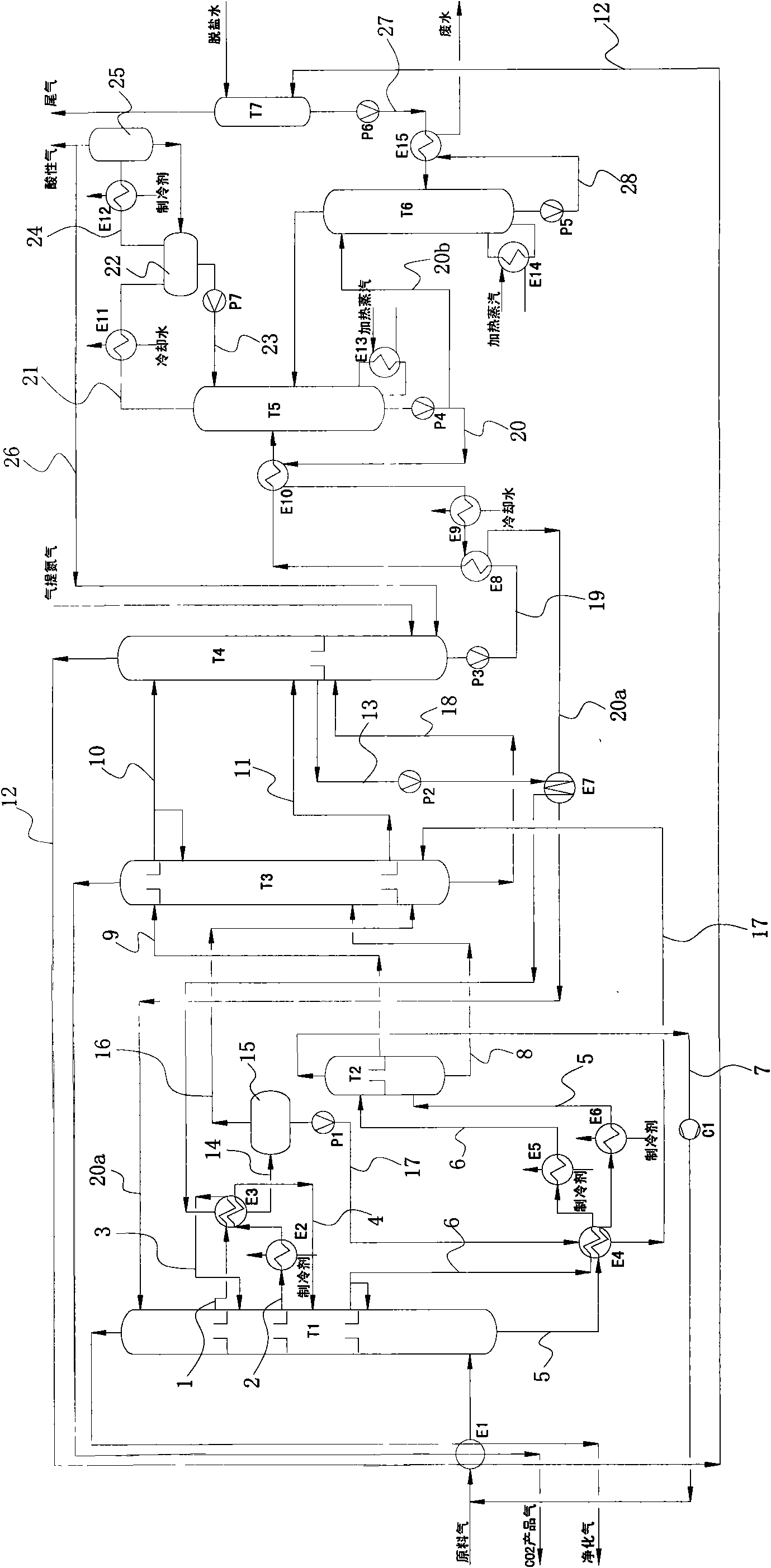
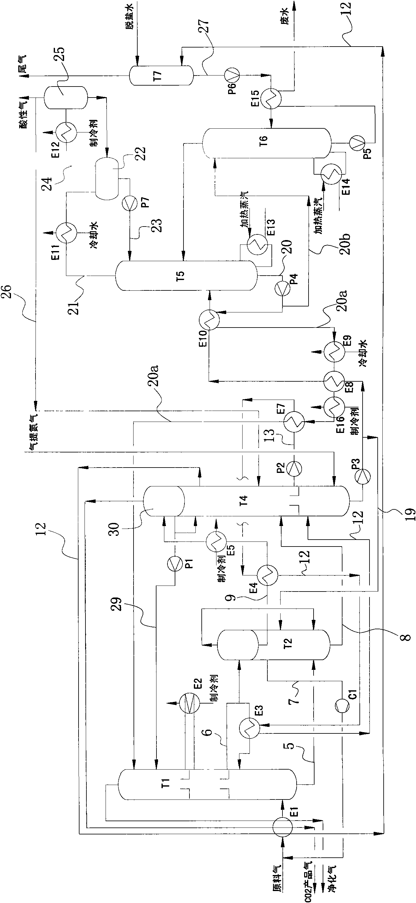
[0035] like figure 2 The split-flow low-temperature methanol washing device shown includes absorption tower T1, medium-pressure flash tower T2, reabsorption tower T4, thermal regeneration tower T5, methanol water tower T6, tail gas scrubber T7, several heat exchangers, pumps, cycle compression Machine C1; the raw gas is first washed by the raw gas scrubber (not shown in the figure), mixed with the circulating gas after washing, and enters the lower section of the absorption tower T1 after being cooled by the first heat exchanger E1; the upper section of the absorption tower T1 for CO 2 Absorption section, the lower section is H 2 S absorption segment.
[0036] The CO in the raw gas after passing through the absorption tower T1 2 The impurities and sulfides are effectively removed, and the purified gas from the top of the absorption tower T1 passes through the first heat exchanger E1 after heat exchange and then exits the device.
[0037] The upper section of the absorptio...
PUM
 Abstract
Description
Claims
Application Information