Voltage detection circuit
A voltage detection circuit and voltage technology are applied in the field of voltage circuits to achieve the effects of small size, simple circuit and low cost
- Summary
- Abstract
- Description
- Claims
- Application Information
AI Technical Summary
Problems solved by technology
Method used
Image

Examples
Embodiment Construction
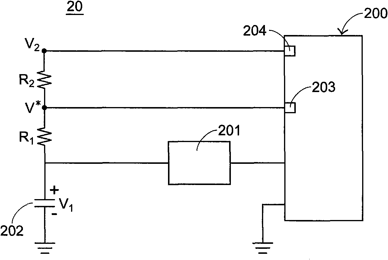
[0049] see figure 2 , which is a schematic diagram of the circuit structure of the voltage detection circuit in the first preferred embodiment of the present invention. The voltage detection circuit 20 includes a micro control unit 200, a boost circuit 201, a power supply 202, a first voltage dividing resistor R1 and a second voltage dividing resistor R2, and the micro control unit 200 includes a general input / output port 203 and a control input / output port 204 , the boost circuit 201 is electrically connected to the power supply 202 and the micro control unit 200, the first voltage dividing resistor R1 is electrically connected to the micro control unit 200, the power supply 202 and the boost circuit 201, and the second voltage dividing resistor R2 is connected to the first voltage dividing resistor R2 The resistor R1 is connected in series to the control input / output port 204 of the microcontroller unit 200. In addition, the microcontroller unit 200 and the power supply 202...
PUM
 Abstract
Description
Claims
Application Information
 - R&D
- Intellectual Property
- Life Sciences
- Materials
- Tech Scout
- Unparalleled Data Quality
- Higher Quality Content
- 60% Fewer Hallucinations
Browse by: Latest US Patents, China's latest patents, Technical Efficacy Thesaurus, Application Domain, Technology Topic, Popular Technical Reports.
© 2025 PatSnap. All rights reserved.Legal|Privacy policy|Modern Slavery Act Transparency Statement|Sitemap|About US| Contact US: help@patsnap.com