Discontinuous foaming agent control lead-in system and method

A technology for introducing a system and a control system, applied in the field of polymer foam plastic processing, can solve the problems of increasing the complexity and production cost of the gas introduction system, increasing the processing accuracy of the supercharger, the electric control accuracy, and the local gas concentration, etc. The effect of industrialized production, low cost and convenient operation

Inactive Publication Date: 2009-12-30
BEIJING UNIV OF CHEM TECH
View PDF4 Cites 7 Cited by
  • Summary
  • Abstract
  • Description
  • Claims
  • Application Information

AI Technical Summary

Problems solved by technology

In the foaming agent introduction system and method, the on-off valve of the outlet and / or inlet of the gas collection tank is closed and / or opened once as a gas injection cycle, and only one gas injection cycle can be accumulated in the gas collection tank once in a gas injection cycle. The foaming agent in the injection molding machine is injected into the polymer melt in the injection molding machine. If the foaming agent accumulated in the gas tank is introduced into the polymer melt at one time during a plasticizing cycle of the injection molding machine, due to the gas The diffusion rate is very fast, such as for N 2 , when the ratio of the pressure in the gas tank to the pressure of the polymer melt is 2, 11.5g N 2 The time to introduce polymer melt is only 1.0×10 -6 ms, and for discontinuous processing techniques such as injection molding, the time of a plasticizing cycle is generally 1 to 10s, so that it cannot be guaranteed that the gas is introduced uniformly throughout the plasticizing cycle, resulting in high local gas concentration, and the initial mixing depends on After the shearing of the screw is completed, the subsequent plasticized melt can only rely on the diffusion of gas in the storage chamber to reach a homogeneous solution of polymer melt / foaming agent, which will take a long time
This will cause the uneven distribution of gas and melt in the storage chamber, the local gas concentration is high, and it cannot be completely dissolved in the melt, and the part does not contain foaming agent, which will affect the uniformity of the product and the stability of the production process. This technical solution is only applicable to small injection molding machines with a screw diameter of 40 mm or less; in addition, the gas introduction system and method also discloses a technical solution, that is, in one injection molding cycle, two or two Attempt to solve the above-mentioned deficiencies through more than one gas collection and gas injection process, which requires multiple starts and stops of the supercharger in one plasticizing cycle, and at the same time cooperates with multiple openings and / or closings of the gas collection tank inlet and / or The on-off valve of the outlet, but since the plasticizing cycle of the injection molding machine is usually less than 30 seconds, or even less than 10 seconds, if multiple gas pressurization, introduction and other steps are to be realized in one plasticizing cycle, the blowing agent is introduced into the system. The pressure adjustment accuracy of the dynamic response process of the supercharger, the action accuracy of the on-off valve and the control accuracy of the control system have put forward very high requirements, which will undoubtedly increase the processing accuracy and electronic control accuracy of the supercharger in the gas introduction system. , the action response accuracy of the on-off valve and the requirements of the control system, thus increasing the complexity and production cost of the entire gas introduction system, and usually it takes 10 to 20 seconds for the gas pressurization to stabilize, so there are considerable problems in the implementation of this technical solution. Difficulties

Method used


Image

  • Discontinuous foaming agent control lead-in system and method
  • Discontinuous foaming agent control lead-in system and method
  • Discontinuous foaming agent control lead-in system and method

Examples


Embodiment 1

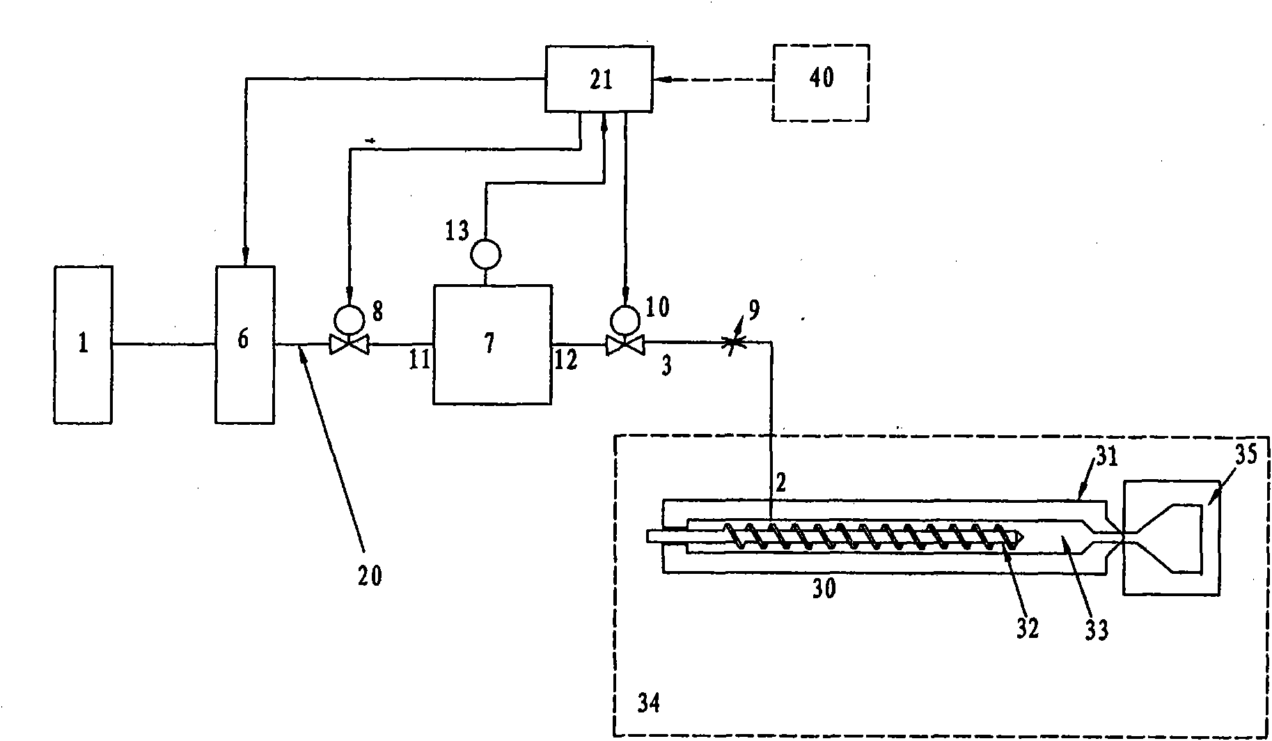
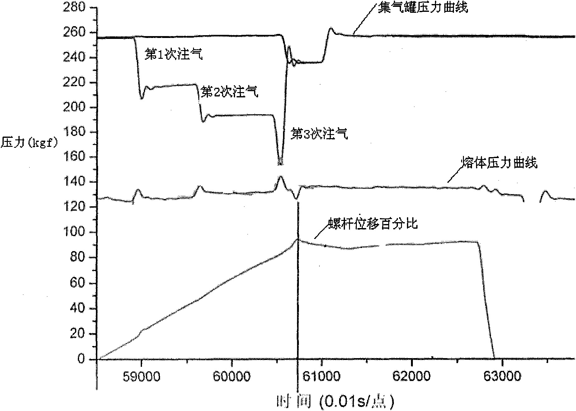
[0050] Injection molding machine T120, screw diameter 36mm, aspect ratio 23.6, a blowing agent injection port is opened on the injection molding machine barrel, the discontinuous foaming agent control introduction system is connected to the injection molding machine through a pipeline at the gas injection port, and the blowing agent The introduction system includes: N 2 Gas tank, with N 2 A pipeline system in which the gas storage tank and the blowing agent injection port are fluidly connected. A gas booster, a gas collection tank, and two channels respectively connected to the inlet and outlet of the gas collection tank are installed in the pipeline system. The volume of the airtight space enclosed between the inlet and outlet of the gas collection tank is 20ml. A pressure sensor is installed on the gas collection tank, and a Flow regulating valve, the flow regulating range of the regulating valve is 0.1~0.5kg / h. In addition, it also includes a control system, which can rec...

Embodiment 2

[0056] The injection molding machine used, the blowing agent control introduction system, and the polymer material used in the test are the same as in Example 1. The opening of the flow regulating valve is 20% of the full scale, the gas injection rate is 0.5%, and the pressure in the gas collecting tank is increased by controlling the supercharger. to 30MPa. In addition, the foaming agent injection method is the same as Example 1, the difference is that in a plasticizing cycle, the screw starts to rotate, and the plasticized material is transported to the storage chamber at the front end of the screw. When the pressure near the gas injection port reaches a stable level, open the shut-off valve at the outlet of the gas-collecting tank. The foaming agent in the gas-collecting tank enters the polymer material melt in the injection molding machine after passing through the flow regulating valve. After 1s, the shut-off valve Close, when the displacement of the injection molding scr...

Embodiment 3

[0059] The injection molding machine used, the blowing agent control introduction system, and the polymer material used in the test are the same as in Example 1. The opening of the flow regulating valve is 5% of the full scale, the gas injection rate is 0.8%, and the supercharger is controlled to increase the pressure in the gas collection tank. to 40MPa. In addition, the injection method of the foaming agent is the same as that of Example 1, the difference is that in a plasticizing cycle, the screw starts to rotate, and the plasticized material is transported to the storage chamber at the front end of the screw, at this time Monitor the pressure near the gas injection port. When the pressure is stable, open the cut-off valve at the outlet of the gas-collecting tank. The foaming agent in the gas-collecting tank enters the polymer material melt in the injection molding machine after passing through the flow regulating valve. It lasts for 0.3s and then stops. The valve is closed...


PUM

PropertyMeasurementUnit
volumeaaaaaaaaaa

Abstract

The invention relates to a discontinuous foaming agent control lead-in system and a method, which are used for introducing foaming agent to high polymer material in high polymer foamed plastic processing. The system comprises: an air source, a foaming agent filling opening and a pipeline system connected with the air source and the fluid phase of the foaming agent filling opening, wherein, the pipeline system is provided with a gas booster, an air collector and on-off valves respectively installed at an inlet and an outlet of the air collector. At least one current restrictor is installed between the on-off valve at the outlet of the air collector and the foaming agent filling opening. In addition, the system also comprises a control system which receives a signal from processing equipment of the high polymer material, calculates the pressure in the air collector, meanwhile controls the action of the gas booster to adapt to the high polymer material processing and outputs a signal to control the opening or closing of the on-off valves at the inlet and the outlet of the air collector, thus realizing the discontinuous filling of the foaming agent. The invention has simple structure, convenient operation, low cost and is convenient for realizing industrial production.

Description

Technical field: [0001] The present invention relates to polymeric foam processing, and more particularly to systems and methods for incorporating blowing agents into polymeric materials for use in polymeric foam processing. Background technique: [0002] At present, a variety of technologies can be used to process polymer materials, including extrusion, injection molding, blow molding, calendering, etc., among which extrusion and injection molding are the two most commonly used polymer material processing technologies. Injection molding refers to the melting of the polymer material in the closed barrel under the action of heat conduction or the plasticization of the screw that can rotate in the barrel, and then the plastic melt is injected into the plastic melt at high speed and high pressure under the action of the plunger or screw. In the closed mold cavity, the molding method of plastic parts consistent with the mold cavity is obtained after cooling and shaping. Almost ...

Claims


Application Information

Patent Timeline
Patent Type & Authority Applications(China)
IPC IPC(8): B29C44/34B29C44/60B29C44/42
Inventor 闫宝瑞信春玲何亚东李庆春张安震胡佳丽李刚
Owner BEIJING UNIV OF CHEM TECH
Why Eureka
Try Eureka